Preface
Surfing the eBay I just have seen an interresting Arduino extension board with an analog joystick, and some buttons. This model has ports for connecting other devices, like Nokia LCD screen and RF module. As I have both, and I just built a joystick myself, I decided to try this prototyping extension.
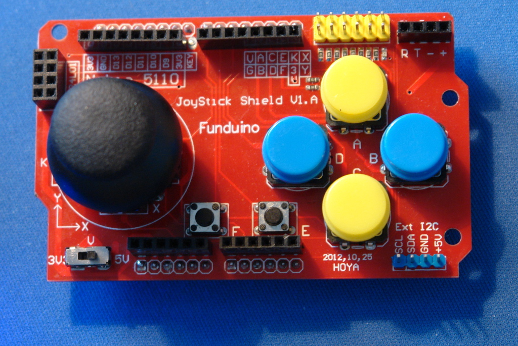
The board is named Funduino JoyStick Shield V1.A, and branded as HOYA with a date 2012.10.25.
Basic functionality
First of all the board has 2 analog (joystick) axes and 7 switches: four direction for the right hand, two function buttons, and one by pressing the joystick.
| Name | Meaning | Arduino pin |
| X axes | A0 | |
| Y axes | A1 | |
| Button A | Up | D2 |
| Button B | Right | D3 |
| Button C | Down | D4 |
| Button D | Left | D5 |
| Button E | Func. Right | D6 |
| Button F | Func. Left | D7 |
| Button K | Joystick Action | D8 |
Ports
Nokia screen FAIL
PCD8544 breakout panel is said to be attached to the marked pins. I don’t know how it is about to be, but that is just not right. You cannot connect default pinout preakout board to this pin order.
| Board port pin order | 3V3 | GND | D13 | D12 | D11 | D10 | D9 | 3V3 |
| Regular Nokia breaout pin order | RST | CS | DC | DIN | CLK | VCC | LIGHT | GND |
As you see, the GND, and 3V3 (VCC) pins just cannot do not match any ways. If you can get a screen breakout with the above pinouts, you can connect it.
RF port
The RF port pinout is:
| NC | D12 |
| D11 | D13 |
| D10 | D9 |
| 3.3V | GND |
Fortunately that matches with my RF24L01+ module.
I’ve wrote an article about RF24L01+, that you can read here.
BlueTooth port
The port labeled with BlueTooth have the labels R, T, -, + on the pins. The + connected to 3,3 Volts, the – connected to the ground, the T is connected to Arduino D0 pin. The R is connected to D1, but not directly. Between R and D1 there is a 1K resistor.