See video explanation of this article here:
Preface
Rotary encoders are pretty cool and easy way to interact with our software.
However it is not straight forward to achieve trusty operation with it. The problem in the physical characteristics of these devices, that I will explain in this essay.
The second most problematic thing is that there are plenty driver implementations out there for Arduino what are mostly junk. So I decided to build one myself.
And here we arrives to the third problem, mainly the explanation can be found in the Internet in the topic are likely to forget to mention some key attributes. So I will start with this.
Note, that I have one kind of rotary encoder, your may differ from mine.
Physical characteristic
For the reasons I’ve mentioned above, I analyzed the physical responses on an oscilloscope. And since personally do not own one, I’ve build one from the Arduino.
You can download home made oscilloscope code here: Dual Channel Oscilloscope
In this photo you see, that in my setup, for a clockwise (CW) turn the following change sequence appeared. Note that this is one tick in the switch.
Also note, that I have pull-up resistors for the pins.
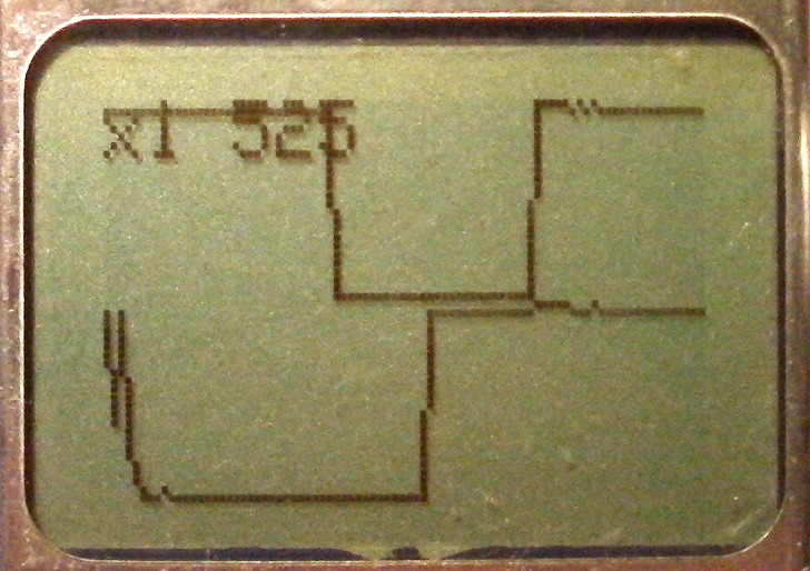
When turning clockwise (CW):
| B down | A down | B up | A up |
When turning counter clockwise (CCW):
| A down | B down | A up | B up |
From this tables you may already see, that if you switch A with B (e.g. you don’t know which leg is what pin), than you will detect an opposite turning direction. Also, if you have pull-down resistors, than you got the opposite results.
What is missing from most explanation, is that the above sequence is one tick in rotation. So the controller has a definite physical stop after a sequence, and the sequence will repeat on every tick. And in most cases we need to measure one tick.
The other thing needs to be mentioned is the bouncing. So that one change in real word may contains some more rapid alternating changes before reaching the stable position.
But our Arduino is so fast, that it can detect these bouncy changes as individual actions. One may recommend you to put a small capacitor parallel with the switch, to smooth up this spikes. But as products from different manufacturer may vary in this characteristic, even the characteristic of one switch may change by age, I will try to solve this in the software.
E.g. ignore further change upon one already occurred.
Logic
From the above table we can figure out various logic solutions, but keeping in mind, that we want to detect exactly one tick, and need to take care about bouncing.
Full cycle method
In the first method I always detect varied changes. So if pinA is changed, than I will wait for pinB change, this way I handle the bouncing. Moreover, I try to detect exactly the same sequence you can see above.
This logic has 5 states: resting, step1, step2, step3, step4, where you can read the meaning of a step from the above table depending on the direction. And yes, we also need to take care about the direction.
For this method I need to set up a watchdog, in case something goes wrong not to let our driver in an illegal state.
Event state check method
If you study the state change above carefully, you may recognize the following fact. When turning CW, pinB goes high while pinA is low. On the other way round pinA goes high, while pinB is low. You will never find this event anywhere else. So we can say, that if this event occur, we have a hit.
That’s fine. But we still need to take care about the bouncing. Let’s say, that we have two states: EVENT_OCCURRED, EVENT_CLEARED. In this manner, we will clear the (CW) state, when pinB goes low, while pinA is high. For CCW: when pinA goes low, while pinB is high.
Voila, we handled the bouncing.
The nice thing in this, that we do not need a watchdog.
Implementation
It is not a good idea to process complicated things in an event handler. And as we do want to do the least things must be done in an event handler, I’ve called my good old trusty timer manager “SoftTimer” for this job. (This is especially needed for the mode with watchdog.)
I have implemented both solution, and it turned out that the second is the winner. So I did populated the driver of this as a part of my Arduino SoftTimer library for free. Enjoy!