Wiring
This is the pin mapping we have for the onboard components.
Arduino pins
| D7 | RF port pin 3 (RF_CE) |
| D8 | RF port pin 4 (RF_CS) |
| D9 (PWM) | Motor B1 |
| D10 (PWM) | Motor B2 |
| D11 (SPI MOSI) | RF port pin 6 |
| D12 (SPI MISO) | RF port pin 7 |
| D13 (SPI SCK) | RF port pin 5 |
| A4 (I2C SDA) | 10DOF port pin 5 |
| A5 (I2C SCL) | 10DOF port pin 4 |
This is the same, but from the other direction
RF port pins
| 1-GND | 2-VCC – 3.3V |
| 3-CE – D7 | 4-CSN – D8 |
| 5-SCK – D13 | 6-MOSI – D11 |
| 7-MISO – D12 | 8-IRQ – Not connected |
10DOF port pins
| 1 VIN | 5V |
| 2 (3V3) | Not connected |
| 3 GND | GND |
| 4 SCL | A5 |
| 5 SDA | A4 |
| 6 (M_DRDY) | Not connected |
| 7 (G_ADO) | Not connected |
| 8 (G_INT) | Not connected |
Extension port pins
This is the extension port pin-out. Top view.
| GND | D3 | |
| GND | D2 | |
| GND | D10 (shared with Motor B2) | |
| GND | A3 | 5V |
| GND | A2 | 5V |
| GND | A1 | 5V |
| GND | A0 |
Dual color sensor extension panel
Logical:
| A0 | Sensor1 |
| A2 | Sensor2 |
| A3 | Light out RED |
| D2 | Light out GREEN |
| D3 | Light out BLUE |
Physical (top view):
| GND | D3 – BLUE OUT | |
| GND | D2 – GREEN OUT | |
| GND | D10 – Free / Motor B2 | |
| GND | A3 – RED OUT | 5V |
| GND | A2 – Sensor2 | 5V |
| GND | A1 – FREE | 5V |
| GND | A0 – Sensor1 |
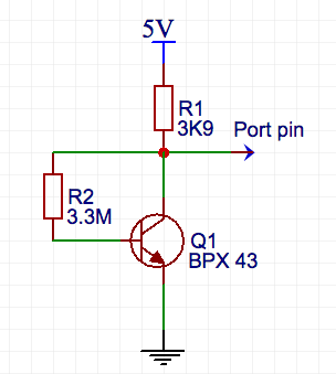
BPX 43 wiring