I always felt the need of a portable monitor. First of all, because I did not had a flip-out screen on my previous camera. But it is also very handy when testing hardware, that requires a screen. But of course it can be used as a secondary monitor as well.
The screen I bought for this project is has the following properties.
| Controller type | VS-TY2662-V1 |
| Screen type | HSD070PWW1-B00 |
| Power | 5~18V |
| Resolution | 1280 x 800 |
| Screen size (millimeters) | 162 x 106 x 4.4 |
| Offsets mm (top/bottom/left/right) | 7.4 / 3 / 4 / 5.4 |
Shopping links (affiliate):
- 7Inch HDMI VGA Driver Board HSD070PWW1-B00 & 1280X800 IPS LCD panel
- 5pcs 18650 Lithium Battery Charging + Protection Module
- 1S Lithium Battery Capacity Indicator LED Display Module
- 10pcs 1/4″ to 3/8″ Reducer Screw Adapter for Tripod Mount Nut
- 30pcs 5x2mm Round Disc Neodymium Magnets
- Branded 12V 1A DC Wall Adapter (5.5mm 2.1mm) 1.8m long cable
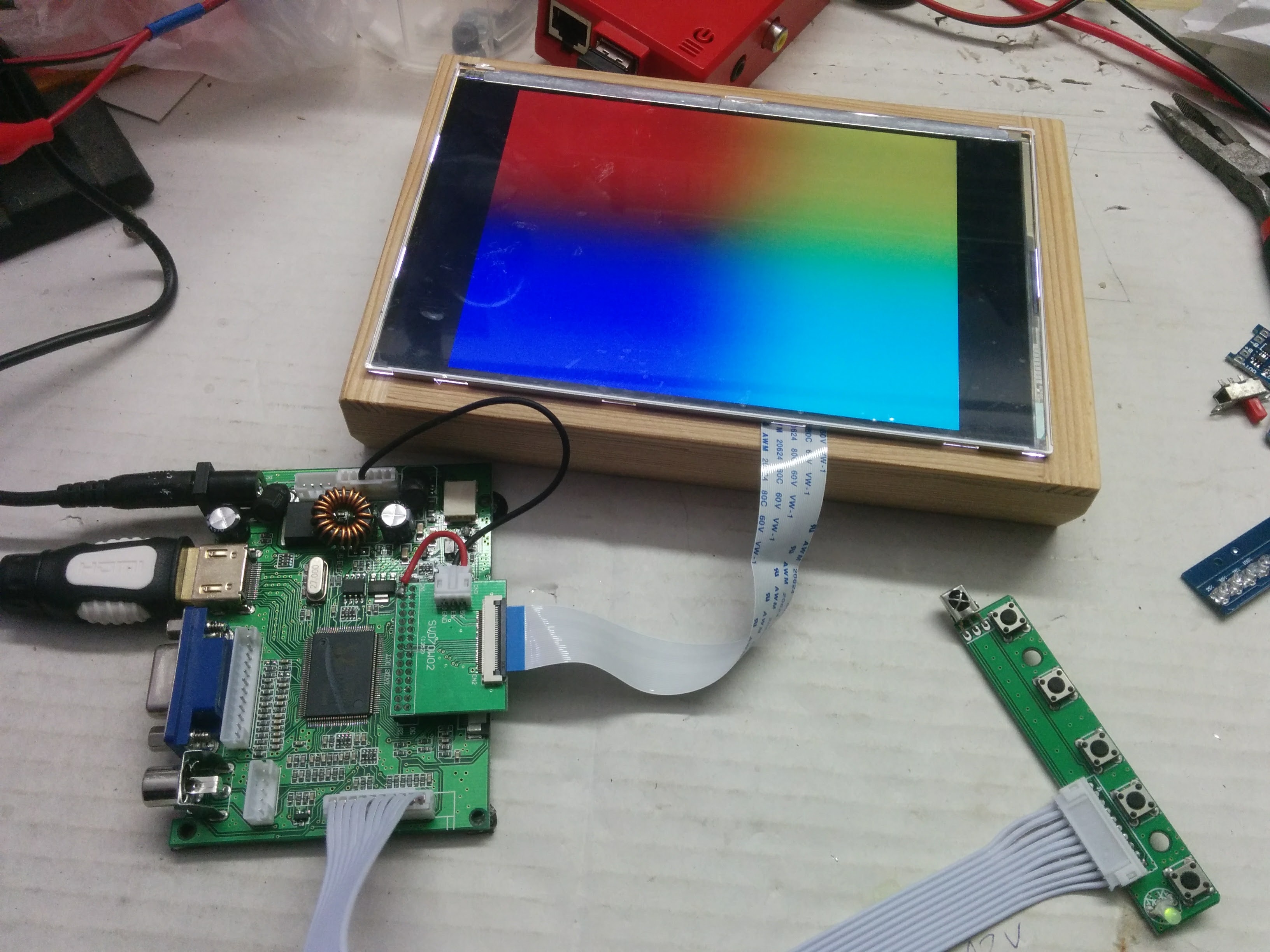
It features HDMI, VGA, composite video inputs, but does not handle audio.
Note, that some HDMI modes of this panel gains too much power for the charger module, so in some cases the you might expect an unstable behavior when operating from batteries. But it is not destructive. So I recommend to keep a wall adapter handy, when using HDMI.
Building the box
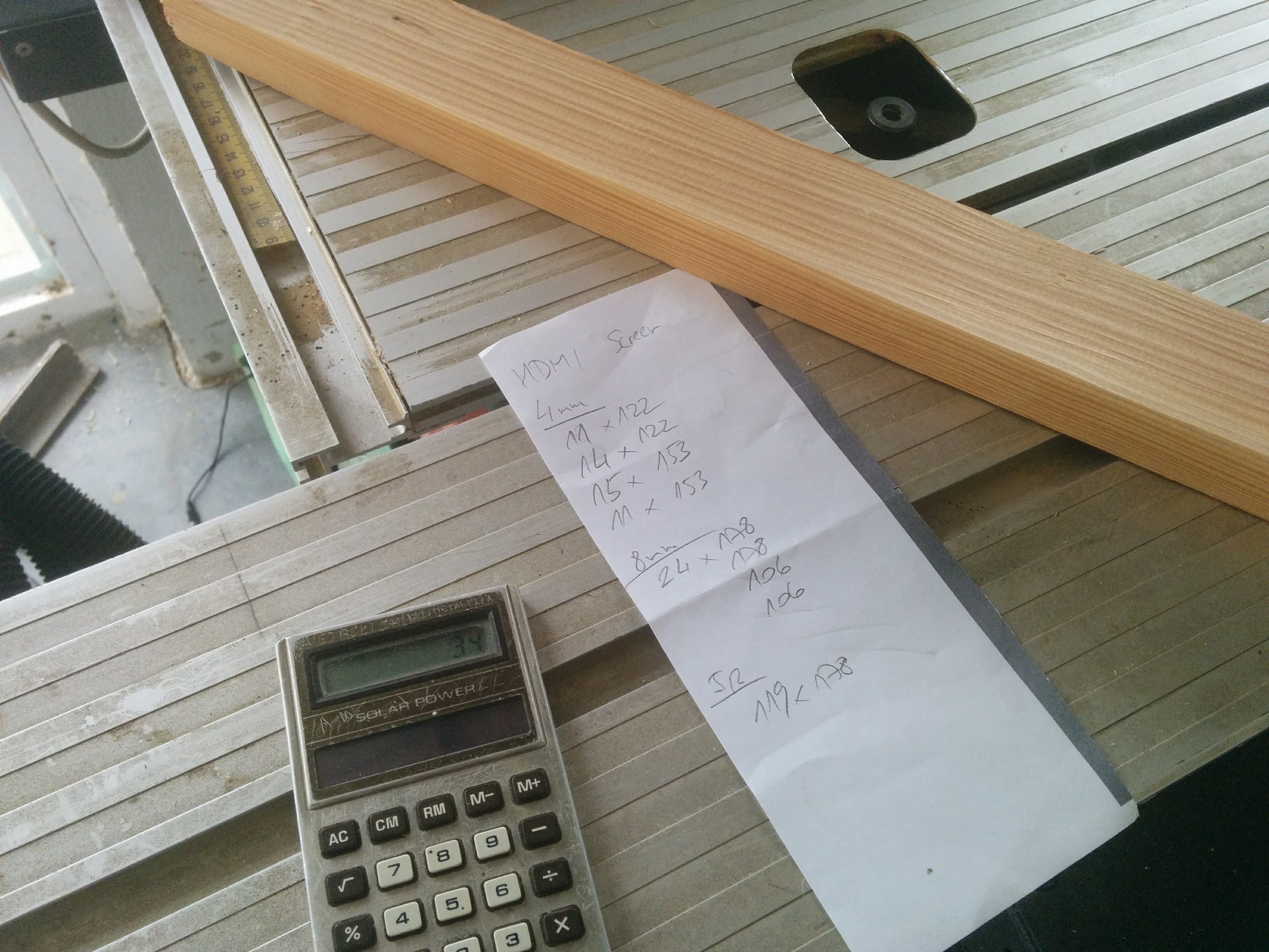
Before the build, I have made a lot of measurements, and designed the body.
Download the design – PortableHdmiScreen-02
I have made the whole body from a single strip of larch. I did not wanted to use plywood this time, because I wanted the nice wood gran to be displayed. So first I have cut the designated pieces for the backer board. And then all the other pieces, according to the design.
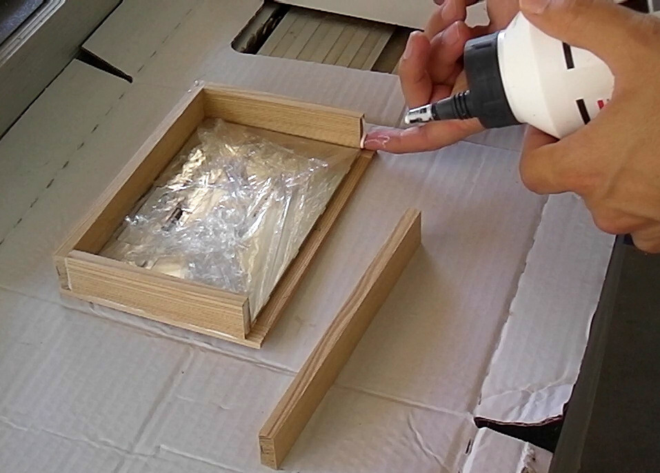
I have used a right-angle jig when gluing the pieces together. This is going to be the front frame and the sides. I have placed the actual screen in the frame, when gluing on the last pieces. (Of course the screen was well wrapped.)
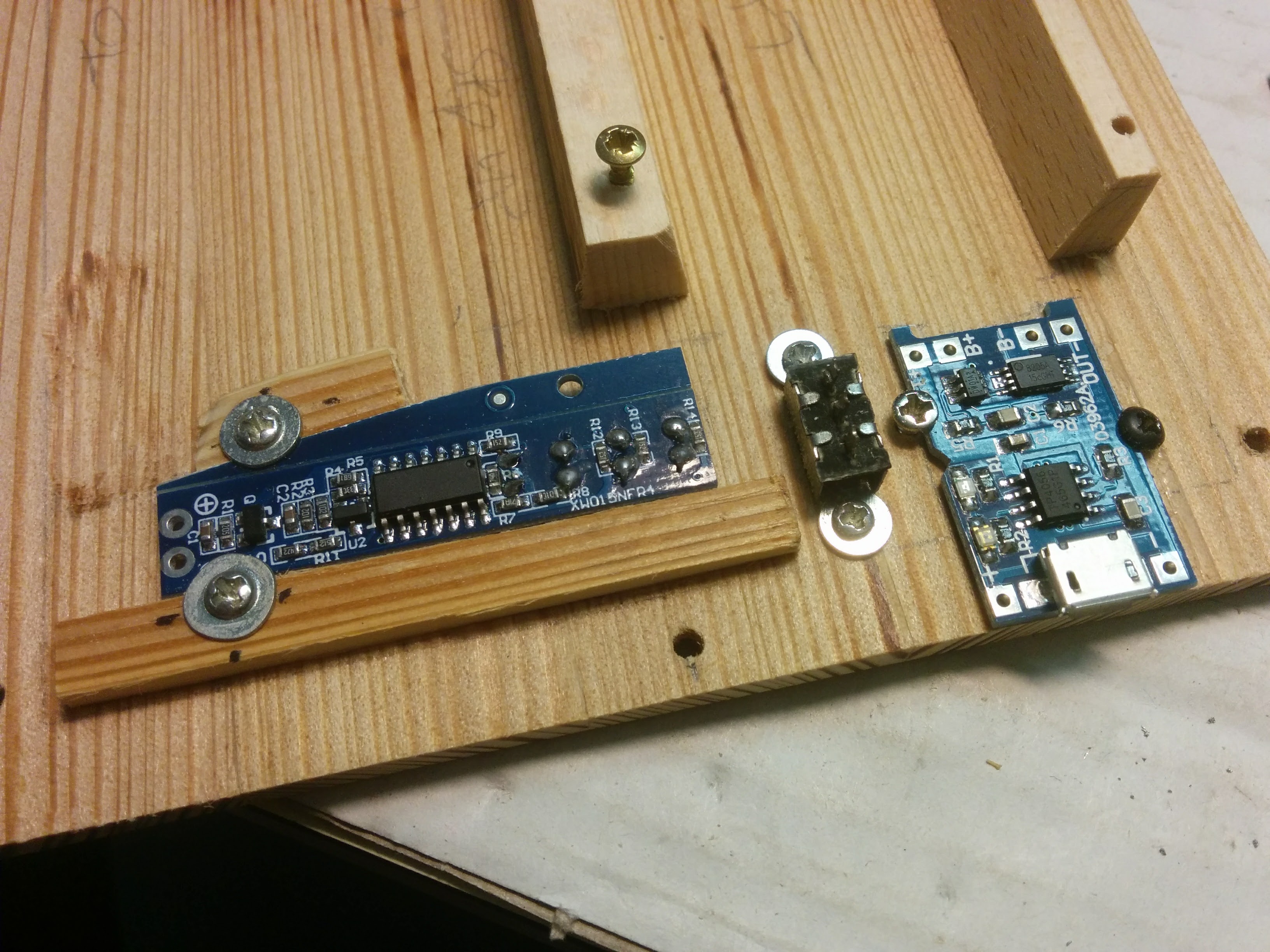
Preparing the electronics
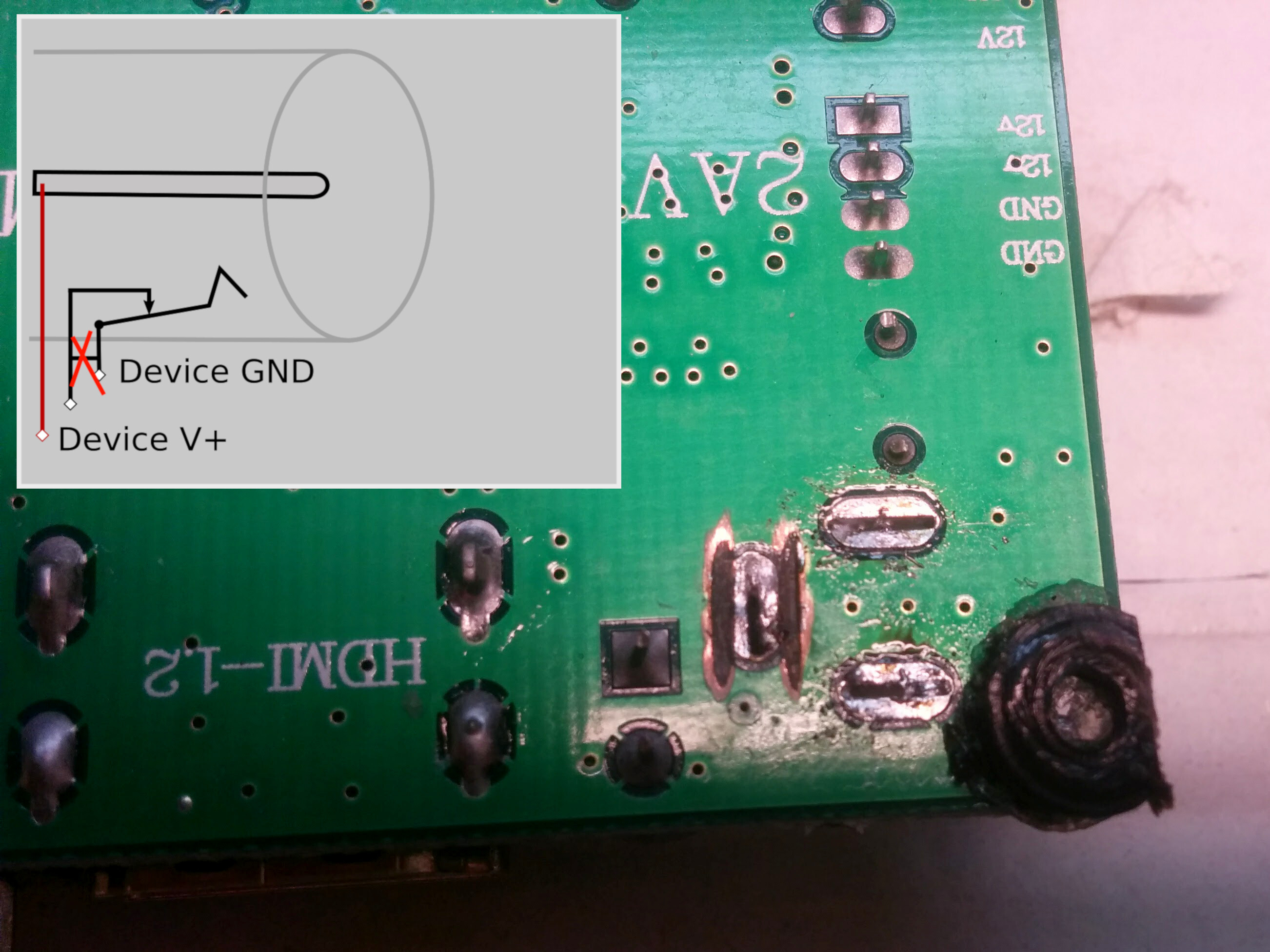
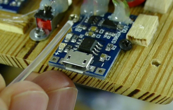
I wanted the unit to be able to work from both an external adapter and from internal batteries. For this I need to modify the DC plug, so that it cuts the internal power, when a plug was connected. For that I needed to remove the DC plug, and then cut the traces from the left connection at both sides of the PCB. The DC plug was then soldered back to its place.
The charger circuit, the battery level indicator circuit, and the switch was mounted well into the backer board, as they will be used actively. A cradle was formed to the batteries.
The stand
I was started to experiment with some stand designs. In the end I was came up with this flip-out stand.
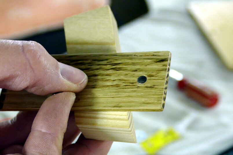
I have cut a piece of hardwood with the designated length and a bevel at one end. Holes were drilled very carefully for the fishing line. (The flip-out leg was attached with fishing nails.)
It clicks-on to the frame with magnets, that are synced into both the frame and the stand piece.
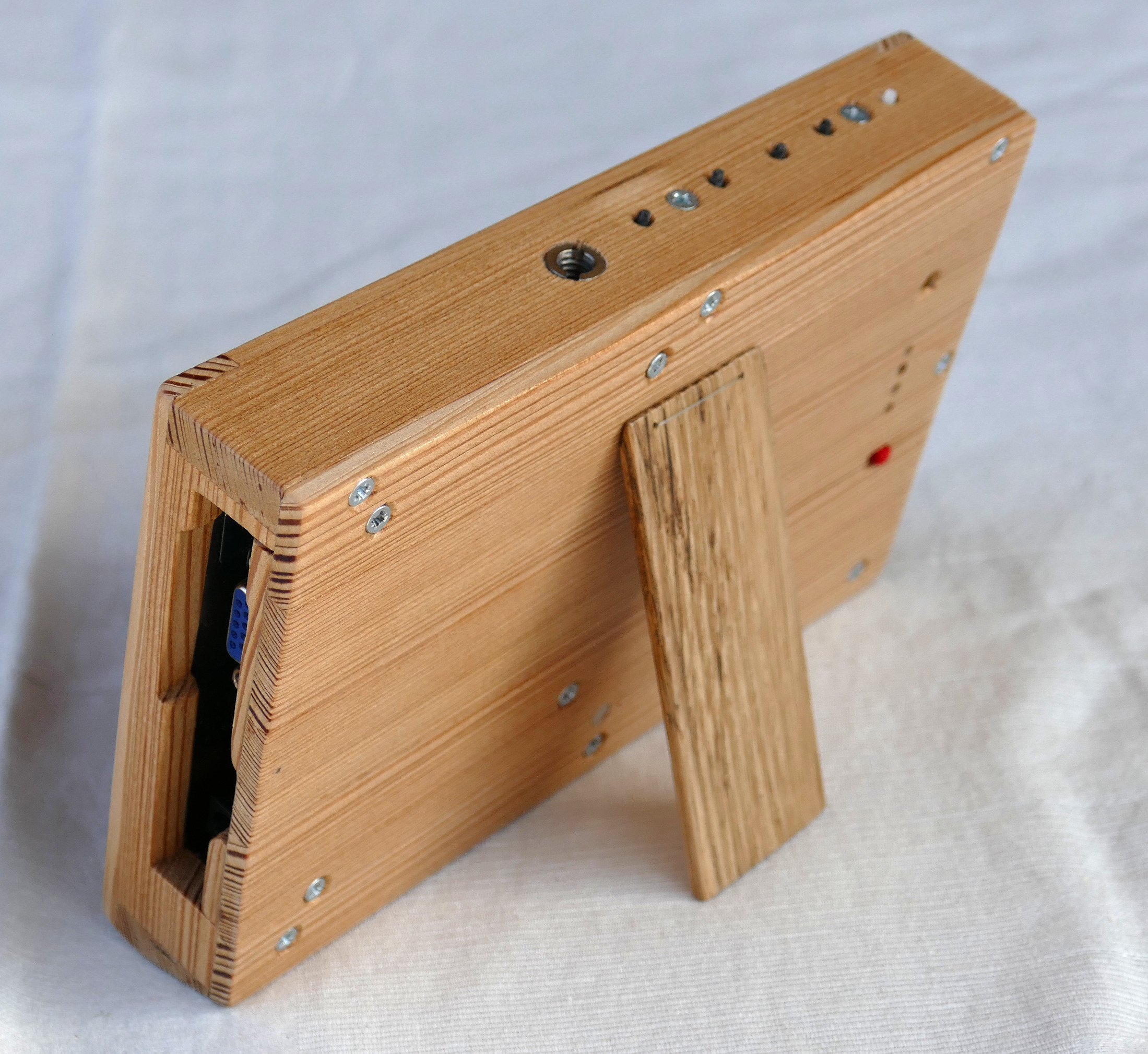
Finishing the body
I have realized, that the backer board is likely to curve, so I have attached extra pieces here and there.
I have predrilled the hole for the tripod accepting nut, than grabbed a bigger drill-bit for the indentation, than made the final cut for the threads. The thread for the insert was cut by the insert itself. I used a monopod to drive in the insert. And repeated the same process for the top mount nut.
After that, all the woodworking job is about to be done, so I have start the finish with a good sanding session. And then several coats of stain. (With sending between with 800 grid sandpaper.)
After the stain was dry I have glued the magnets with superglue.
As the stain was applied at one side at a time, the backer board was bent, but it is not so bad, and the screws will bend it back to place.
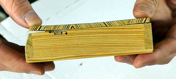
The fishing line was drove through the holes, and a spring was formed from a wire on the other side.
Wiring up
The battery, the charger, the indicator and the switch has its place already prepared. A step-up converter needs to be attached. I don’t go too crazy with this: it is attached with double sided tape. If it come loose sometimes will not cause any trouble any way.
The driver board is attached, and all what’s left was wiring.
Final assembly
The screen needs to be inserted as first. It was fixed with toothpicks and some minimal hot glue.
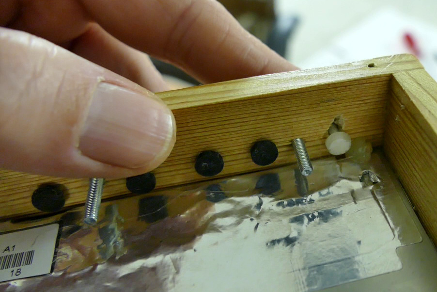
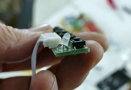
Than comes the button panel. The button pins were 3D printed, and the power button pin is printed from a translucent material, and the power indicator LED was modified, so it has an orientation of lighting towards to the translucent pin.
The loose wires were also hotglued.
A translucent wire was inserted above the charger indicator LEDs, to direct the light outside the case.
And the case can be closed.