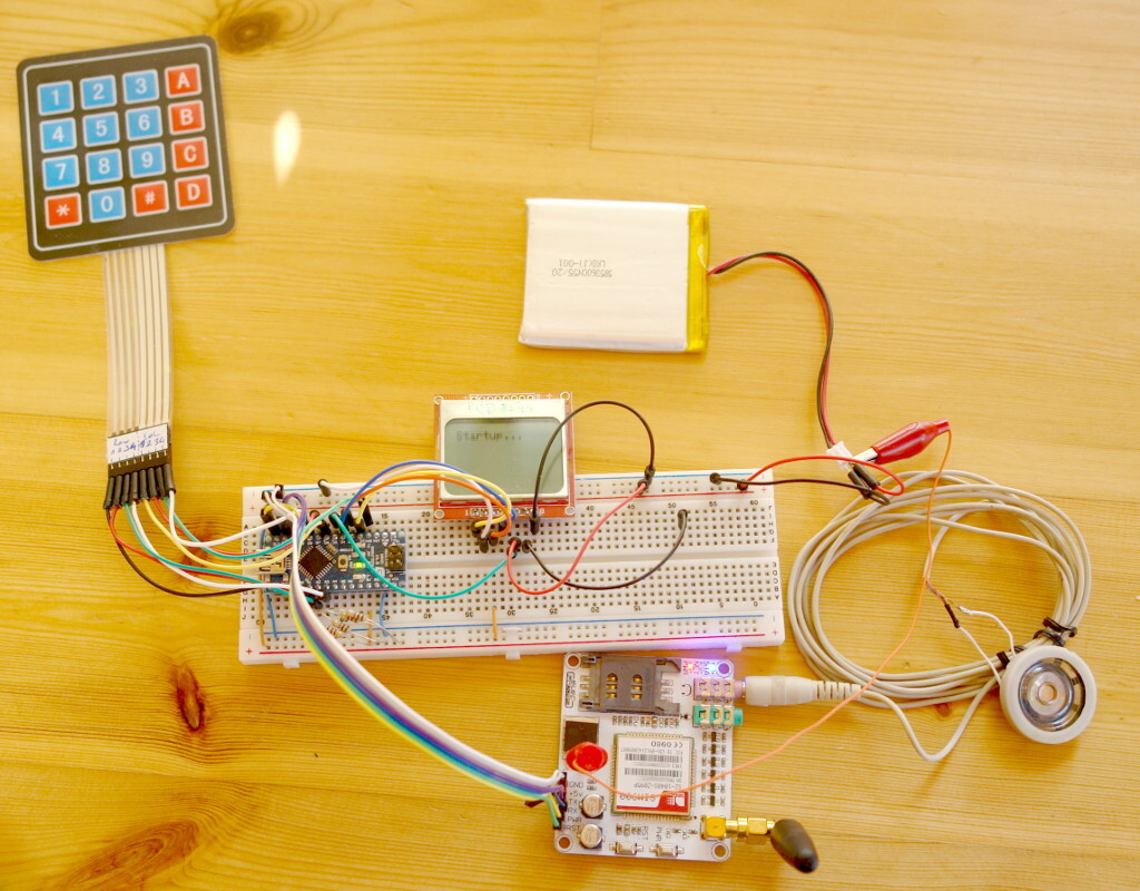
I have a cheap SIM900 based module for Arduino. I would like to create a Nokia 5110 like phone from it.
Main components
I want to build a simple hardware and write a modular software for it, so the phone functions can be extended later on.
I want to achieve the following functionality (what is mostly provided by the SIM900 chip).
- Make call
- Send SMS
- Receive call
- Use phonebook on the SIM.
What will I need for this project.
- A SIM900 (or alike) module with the required peripherals like the simcard holder on a breakout board.
- A PCD8544 display
- 16 keys keyboard matrix
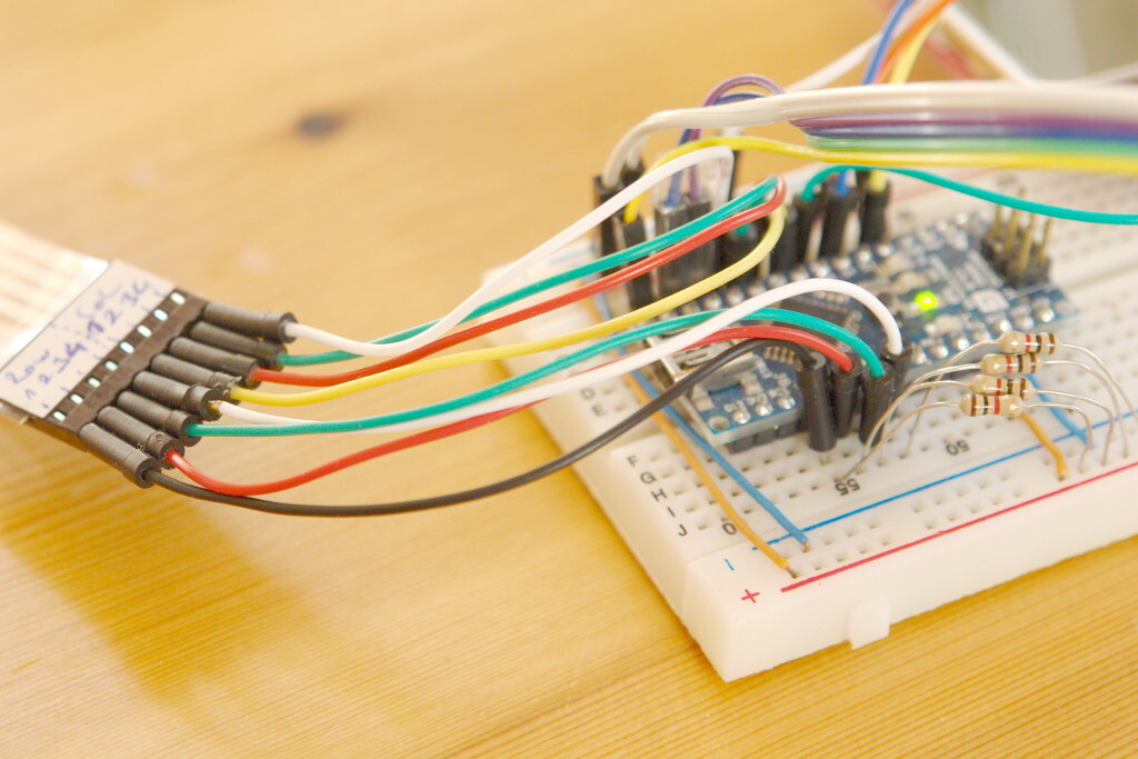
- Arduino
- (battery)
- Software
First I will drive it from USB, later on I will move on to use it with battery.
Power
I already know that mobile communication will need much current (peek 1Amp!). That is something to keep in mind. The best will be to power the SIM900 directly from the LiPo battery.
Wiring and Libraries
PCD8544 LCD
For the LCD I will use the Adafruit PCD8544 library. Connecting the pins:
| Device PIN | Logical | Arduino PIN |
| 1 | RST | D2 |
| 2 | CS | GND |
| 3 | DC | D3 |
| 4 | DIN | D4 |
| 5 | SCK | D5 |
| 6 | 5V | |
| 7 | Backlight (LOW=ON) | D13 |
| 8 | GND |
Note, that CS was directly connected to the ground as no other SPI devices are about to be used.
So the display will be initialized as follows:
#include<Adafruit_GFX.>
#include <Adafruit_PCD8544.h>

Adafruit_PCD8544 display = Adafruit_PCD8544(5, 4, 3, 2);
SIM900 breakout module
For testing purouse I will use SoftwareSerial. So RX, TX lines will be connected to some digital pins.
| Device PIN/Logical | Arduino PIN |
| GND | |
| +5V | |
| TX | D10(RX) |
| RX | D11(TX) |
| PWR | D12 |
| RST | GND |
#include <SoftwareSerial.h>

  SoftwareSerial mySerial(10, 11); // RX, TX
Unfortunately SotwareSerial does not read well with the default baud rate of the SIM900, I will reduce the baud to 9600. (I’m not going to use data connection anyways. But I can always switch to hardware serial for higher baud.)
As now we’ve got a working circuit, we shall run a little test on it. I’ve started the GSM code according to the tutorial provided by the Cooking Hacks guys.
Keypad
We have left four digital pins + the two serials, and the seven analog pins. For the 4×4 matrix keypad we would need 8 digital pins. At least for the Keypad library. Now using a keyboard matrix is sending and receiving values on the pins, so I could have write my own library using analog pins for sensing valued. Also, the analog pins has PCI, so I could have write an event driven solution. But I don’t want to.
Instead I find this interesting: http://experimentaltechnik.com/matrix-keypad-pin-reduction/
This solution uses only one analog pin for reading the pressed key, unfortunately needs some wiring.
And I’ve ended up with the following solution.
I’ve inherited the Keypad library to be used for analog pins. The idea is that the colums still needs digital pins (for sending the test signals), but the rows are now connected to the analog pins for receiving values. The analog pins must be pulled up to 5V with resistors. (I’ve used 1K resistors.)
The mod is:
#ifndef KEYPADANALOG_H
#define KEYPADANALOG_H

class KeypadAnalog : public Keypad {
public:
  KeypadAnalog(char *userKeymap, byte *row, byte *col, byte numRows, byte numCols)
: Keypad(userKeymap, row, col, numRows, numCols) { }

  int  pin_read(byte pinNum) { return analogRead(pinNum) > 512; }

};

#endif
The Keypad.cpp also need to be changed, so that the row pin initialization should be omitted.
void Keypad::scanKeys() {
// Re-intialize the row pins. Allows sharing these pins with other hardware.
//    for (byte r=0; r<sizeKpd.rows; r++) {
//        pin_mode(rowPins[r],INPUT_PULLUP);
//    }
And the usage is:
#include<Keypad.h>;
#include <KeypadAnalog.h>

const byte ROWS = 4; //four rows
const byte COLS = 4; //three columns
char keys[ROWS][COLS] = {
  {'1','2','3','A'},
  {'4','5','6','B'},
  {'7','8','9','C'},
  {'*','0','#','D'}
};
byte rowPins[ROWS] = {0, 1, 2, 3}; //connect to the row pinouts of the keypad
byte colPins[COLS] = {6, 7, 8, 9}; //connect to the column pinouts of the keypad

KeypadAnalog keypad = KeypadAnalog( makeKeymap(keys), rowPins, colPins, ROWS, COLS );

void setup(){
  Serial.begin(9600);
  Serial.println("Ready.");
}

void loop(){
  char key = keypad.getKey();

  if (key){
    Serial.println(key);
  }
}
My wiring for the keypad.
| Device PIN (from left to right) | Logical | Arduino PIN |
| 1 | row 1 | A0 (pulled up to Vcc with 1K) |
| 2 | row 2 | A1 (pulled up to Vcc with 1K) |
| 3 | row 3 | A2 (pulled up to Vcc with 1K) |
| 4 | row 4 | A3 (pulled up to Vcc with 1K) |
| 5 | col 1 | D6 |
| 6 | col 2 | D7 |
| 7 | col 3 | D8 |
| 8 | col 4 | D9 |
Startup
I’ve wired up the prototype. So far so good. Now here comes the tricky part. I’ve wrote a small and ugly testing software for it.
I was facing with several problems.
- As I already mentioned I want to use SoftwareSerial, as I would like to have debug feedback in the hardware serial. So I need to switch to 9600. This is possible, because sending with 115200 works well. So we ask the module to switch to 9600, than we switch the SoftwareSerial to use 9600 as well.
- I need some input method, to enter the pin and to dial a number. So I’ve invented the readNumber method. I use the keypad with the following meanings: “A” – Cancel, “B” – Up, “C” – Down, “D” – Accept
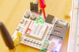
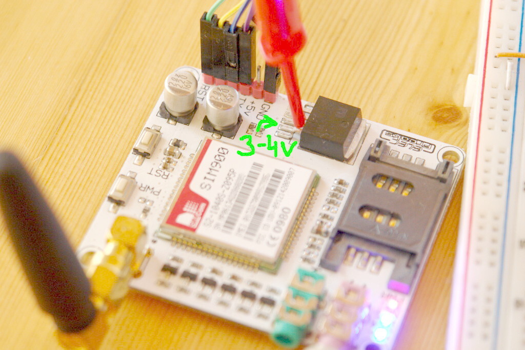
- While connecting to the GSM network the SIM900 drains a lot of power, and the power regulator seems to fail on the board. So I skip the regulator, and connected the Li battery directly on the output of it. (See photo below.) I know, that this is a bad idea, as the Li battery does not stand undervoltage. I will have to figure out something later on.
After solving these problems now I have a working prototype, I can now dial numbers from my on phone.
I will continue with a more complex software solution.