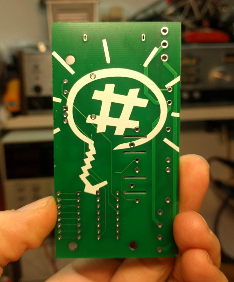
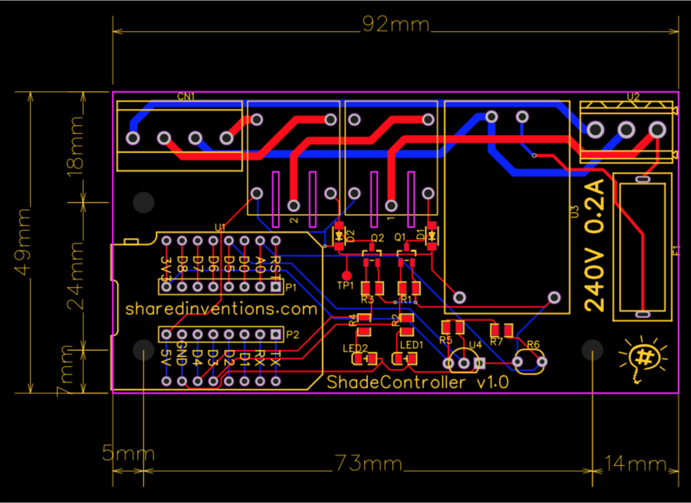
I have designed a module for controlling window shades as a part of my own home automation project.
AC side
The idea of this module is to control shade tubular motors. These motors has four connections: Ground, Neutral, Live1, Live2. Live1 and Live2 gets connected whether you are want to shade to up or down.
This module contains two relays one is to connect/disconnect the live wire, the second is to choose whether the live should be connected to Live1 or Live2.
SAFETY WARNING: Board version V1.0 does not contains any jam-protection. It is highly recommended to utilize a motor that contains protection against jams.
SAFETY_WARNING: The module utilizes high voltages directly. This module is not recommended for ones don’t have experiences handling high voltages.
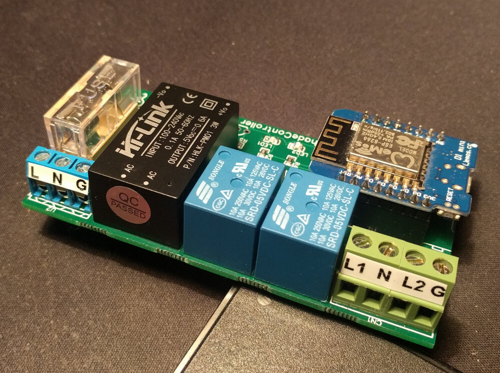
The module also contains the control logic, what is an ESP8266 (Wemos D1 mini) micro-controller. The driving of the relays and the micro-controller requires 5V. A self-contained AC-DC converter (HLK-PM01) is used prepare this 5V from the AC voltage. Note, that the AC-DC controller (and thus the whole module) also can work on 110V AC, but you might need to use 0.4A fuses in this case.
Update to v1.1:
- R8 271 type (10D271K 270VAC) over voltage resistor is added.
- C1 100nF X2 type “across-the-line” safety capacitor is added.
- C2 1nF Y2 type filter capacitor is added.
Control logic
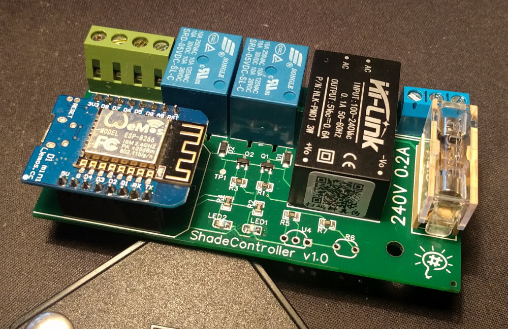
The module is built to accept a WiFi enabled (ESP8266) micro-controller breakout board called “Wemos D1 Mini”. The micro-controller can be programmed from the Arduino IDE via the internal USB interface of the breakout board.
The module uses relays and relay drivers to switch the high voltage. LED lights are also lighting up parallel of actuating the relays.
Options
- Light sensor – The module is also prepared for accepting a photo-resistor for measuring light sensitivity.
- Temperature sensor – A digital (one wire) temperature sensor can be attached to the module.
- Controlling lights – You can certainly control things other than shade motors with this module. In this case you can omit Relay2 and connect the center pin in the place of the Relay2 directly to the upper left on the opposite side with a thick well-isolated wire. This way the L1 is switched.
Parts and costs
- PCB – About $2
- Wemos D1 mini – $3
- HLK-PM01 – $3
- 2x Relay – $1
- Terminals and fuse holder – $1
- SMD components – $1
- Optional: 5mm GL5516 photo resistor – $0.05
- Optional: DS18B20 temperature sensor – $1
(Affiliated links!)
See detailed material list at the end of this document.
PINs
| PIN | Meaning |
| D3 | Relay1 – On/Off |
| D4 | Relay2 – Direction chooser |
| D5 | OneWire Dallas temperature sensor (DS18B20) |
| A0 | Light sensing photo resistor |
Sensing AC load
The idea is that when a potential jam occurs in the mechanics the AC load rises. If we can measure the AC load, we can shut down the motor movement to protect the mechanics (and other valuables).
For measuring AC current we can use a current transformer.
Current transformer
Theory: Current transformers transforms 1/1000 current, thus 20A load will transform into 20mA. The transformer need a load between the outputs. With a 150ohm burden resistor we hope for about 600mV output. The input load should never exceed 1A (actually 0.53A), that is 1mA on the transformer output. If we want 3V output, we need a 3K load resistor.
The output is a small voltage AC signal. We also need a 0.1µF capacity couple capacitor between the signal and the analog input.
See this video for details: https://youtu.be/gvBVxQGS_OU?t=288
Real life: We might utilize pre-built module, that contains an operational amplifier.
AC voltage detection
With the analog input of the micro-controller we can easily measure DC voltage levels. But AC voltage is a completely different thing. You need to restore the sinus AC signal and measure the amplitude of that it with sampling.
Ardunio “Filters” library can do the calculations and can provide AC values from the provided samples.
Arduino Filters library: https://playground.arduino.cc/Code/Filters/
Details on AC analog detection: https://www.instructables.com/id/Simplified-Arduino-AC-Current-Measurement-Using-AC/
Resources
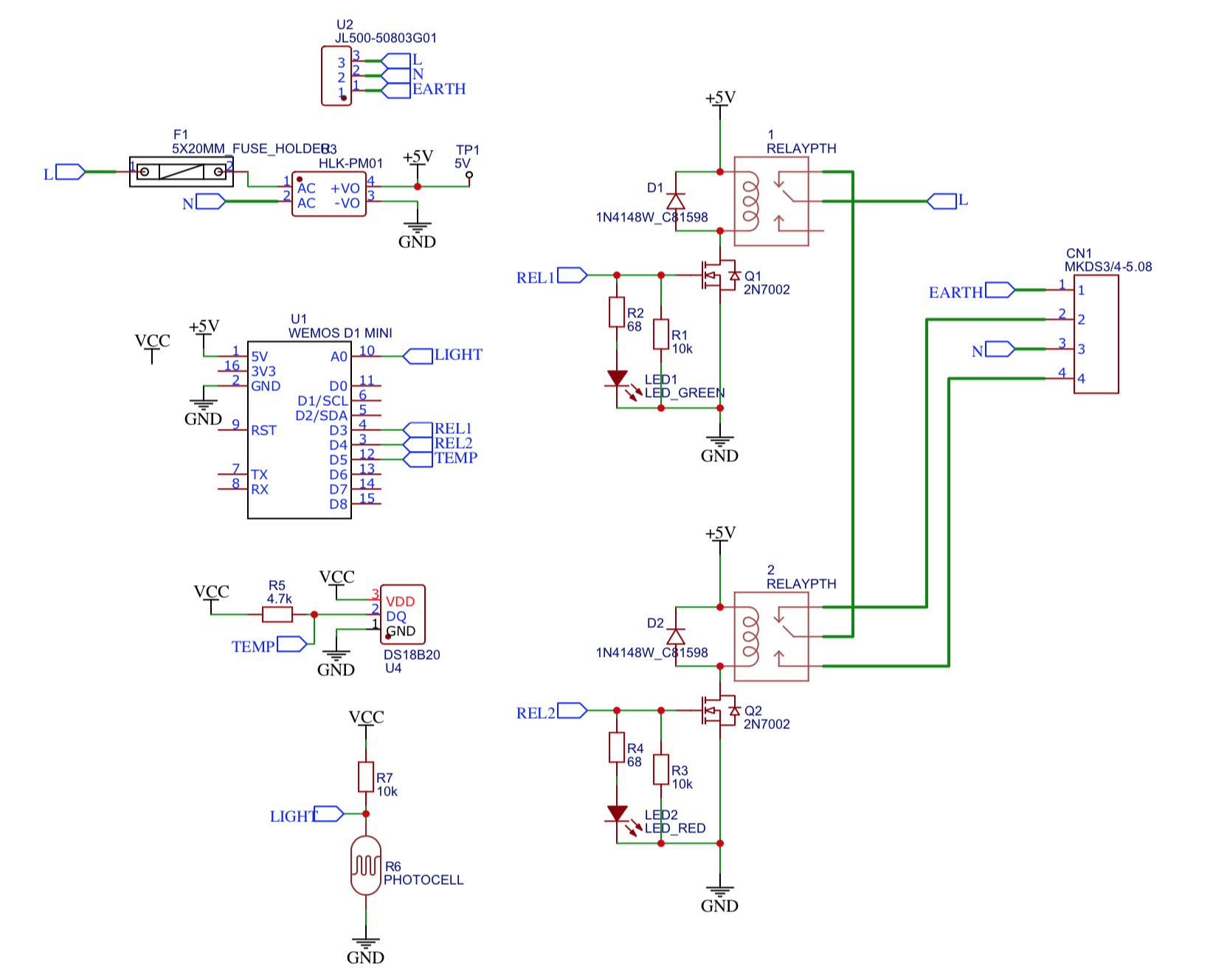
- Schematic: WemosD1Mini-ShadeController-v1.0-Schematic.pdf
- PCB design: WemosD1Mini-ShadeController-v1.0-PCB.pdf
- Component list: WemosD1Mini-ShadeController-v1.0-BOM.csv