Preface
Recently I’ve received an order from China containing lots of cool stuff. One of this is a cheap radio frequency module. I was playing around with this a bit and I’m happy to share my experiments with you.
Kickstart
I had lots of trouble staring up the unit. Fortunately there is an Arduino program called “Poor Man’s Wireless 2.4GHz Scanner”, so I could manage to figure out my wiring problems.
The most common problem with this module is the arrange of the pins. First of all it was hard to figure out the right pinouts, but the more problematic part was that the pins are ordered in two rows. This makes prototyping the board very hard.
The second problem was finding the right Arduino library. The library RF24 was just not right. But the library Mirf worked well.
Wiring
The pinout of the module is not straight forward. When you hold the module, so that the components facing to you, and the crystal is at the bottom, you will have the right order of the pins, so:
1 2
3 4
5 6
7 8
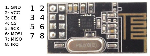
To connect it with the Arduino I’ve used the hardware Spi bus (11,12,13 pins), and used the 9 and 10 pins for CE and CSN, so all five connections are one after each other. So the wiring is:
1 2   1-GND         2-VCC (3.3V)
3 4   3-CE (D9)     4-CSN (D10)
5 6   5-SCK (D13)   6-MOSI (D11)
7 8   7-MISO (D12)  8-IRQ
Please note that this module requires 3.3V power to pin 2. The for the logic level you can use 5Volts. I’ve used the 3.3 Volts output of the Arduino.
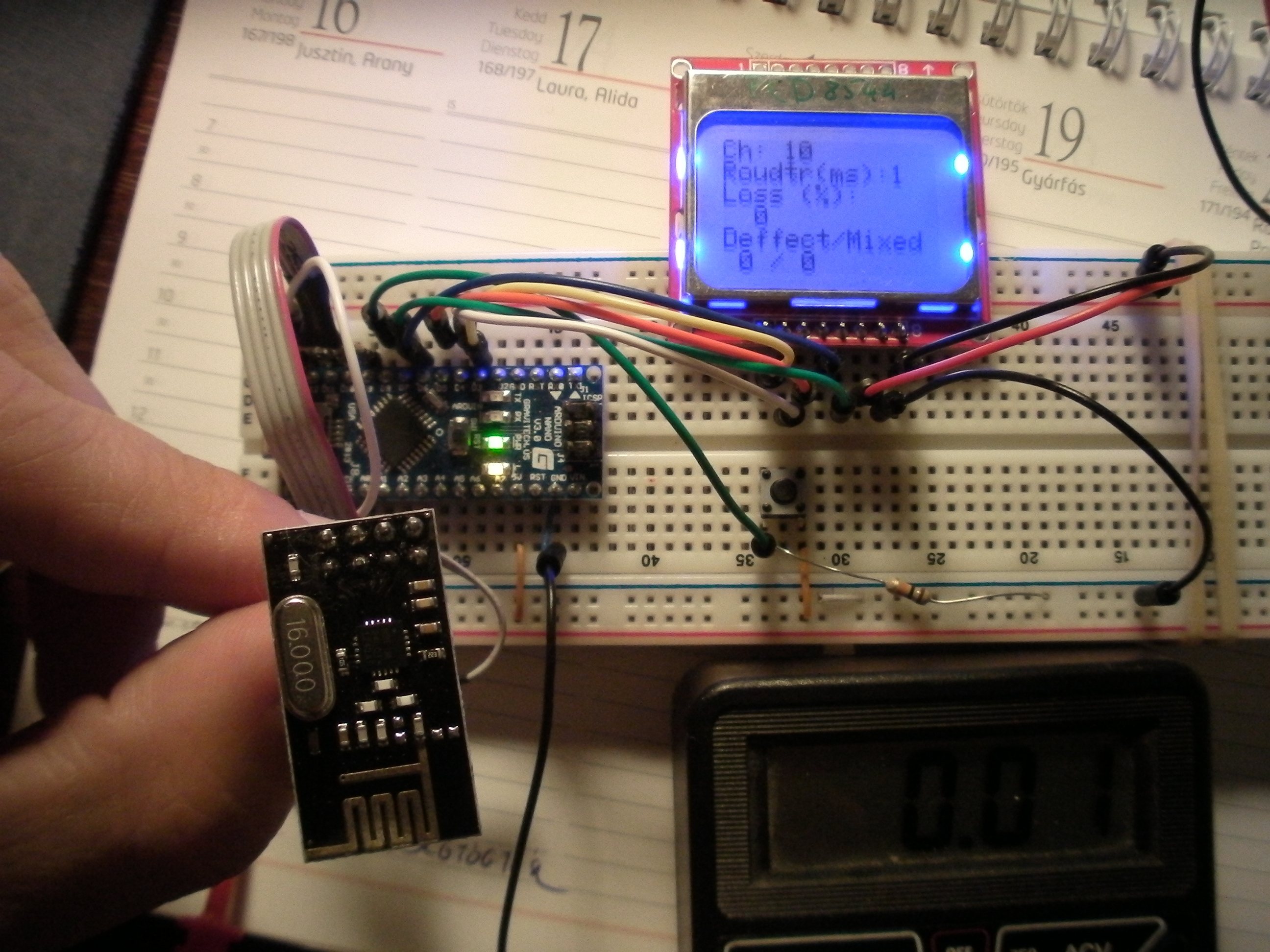
I’ve also hooked up a Nokia LCD display for the “client side”, but in this case you might want to use a regular 16×2 LCD display instead.
There is a switch wired up to make some interaction.
Goal
My goal was to test the unit, how reliable it is. So I was sending date from the “client” to the “server”, the server echos the post, and at the client side I collect statistics about the transfer.
I’ve also made it possible to switch channel in the units. With this feature you can see how can you pass commands from one side to the other.
Software
One of the most important thing is the data you are about to transfer. Now I’ve used a structure for this called RfPacketType. You may use a custom structure of your need, mine is just a sample. This type of data structure can used for transfer. Note how it is used for defining the payload size,
Mirf.payload = sizeof(RfPacketType); // -- define data size
and for the transfer:
Mirf.send((byte *)&packet);
Also note that to maximal packet size (payload size) is 32 bytes. So you need to be sure that your defined structure does not exceed this size.
After all initializations the client sends data to the server, and waits for response. I’ve figured out that a normal handhake is done in about 1 millisecond, so an 50 milliseconds timeout for the response is more than enough.
After the data arrived back some checks are done.
In every LOG_MS milliseconds the statistics are shown in the display.
A channel switching logic implemented. So when the witch was pressed a special command is sent to the server. I case the response arrived switch was performed.
The server side is very similar, but it is free from the statistical junk.
Note: The channel switching strategy is not bombproof. There can be a situation where the server echos back the acknowledge for channel switching and changes to that channel, but acknowledge was lost in “the air”. And the two units looses the synchrony.
→ Download the software from this link.
Observations
The unit seams to be very reliable. It worked indoor through walls, and more than 60 meters when there were no other objects standing between the two units.
I’ve also realized that this unit does not accepts broken data. So I was created a simplified version of the client software.
I’ve measured 0.01 Amperes in 3.3 Volts as power consumption.