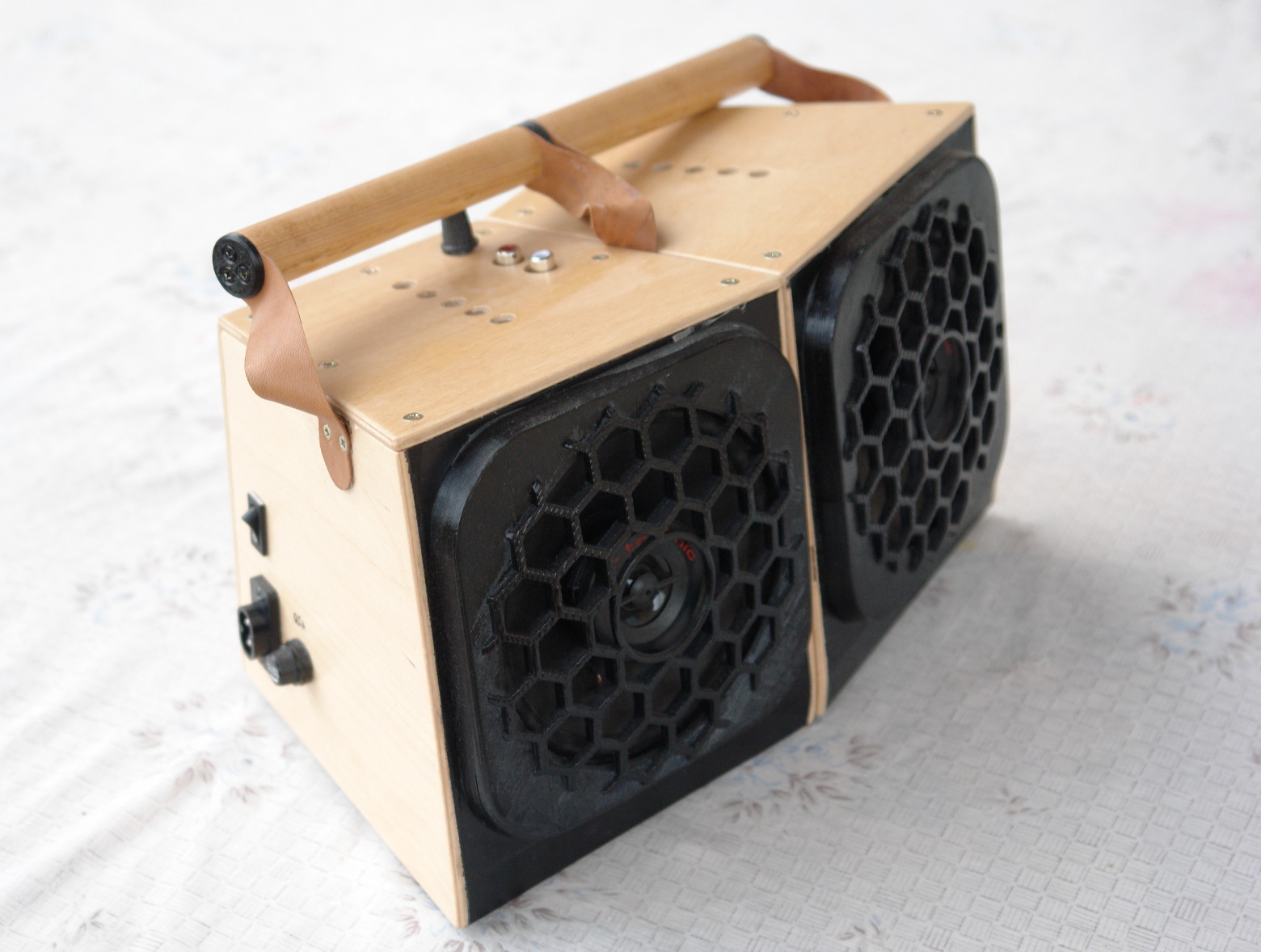
This document is about a speaker case I was built around a TDA2030A amplifier circuit and a 130mm car speaker set.
Preface
The story began some years ago, when I’ve bought a TDA2030A DIY Kit as a Fater-child project to build a power amplifier together.
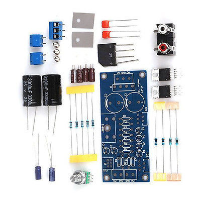
The amplifier was build, but it turned out that we are immediately faced with some complications. It turned out, that the circuit requires +-12V AC power input. That means that a kid of special transformer is required, that converts mains AC to three leads -12V AC / 0 / 12V AC voltage. That means that a box should be created for the transformer, to prevent any contacts for mains leads.
Now if we have a box, than we should include all other electronics as well so why not build a speaker housing that contains everything.
Case design
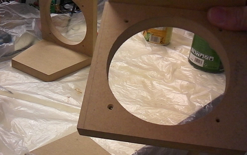
I was looking for rather good quality used speakers, that are still portable. And I was end up with 130mm (5-1/4″) size 2-way coaxial speaker set. This needs a 118mm hole to be fit in.
I have started with a 150mm x 150mm front for the speakers, and a 150×130 size base. The tilt is about 10°, the angel between the the two peaces is about 15°.

The key of this design, is that it does not require you to make exact cuts (what is by the way impossible with the tools I use). Instead, every cut and fit should be made a bit oversized and the final shape will be achieved by sanding down the extra. One thing needs some care however, is that before gluing up the sides pieces the left and right half should be placed side by side to check the fit of the two.
Assembling the case
The bottom (base) and the front peace was cut from 18mm MDF, all other faces were cut from 5mm ply wood.
As you can see on the video. I did not used any measurement tools for finding the position of the next cut, but used the pieces I already assembled to find out the size of the next piece. And when this piece was fixed, that it was sanded flat, and to fit the existing ones.
 Cut bigger, than sand to fit
This was the assembling order of the faces (for both left and right case):
- Face and bottom (base) piece was glued together. – The front part was sanded to the matching size.
- Side pieces was measured and cut to fit the existing pieces. Blocks were added for holding screws. – Side pieces were sanded to fit.
- Same for the back piece.
- Same for the top piece.
So while assembling the case the top part is the last to crew in place.
The side pieces were glued in place. They hold other electronic parts, and most importantly they hold the handle, that requires rigidity.
Preparing the the case for the internal components
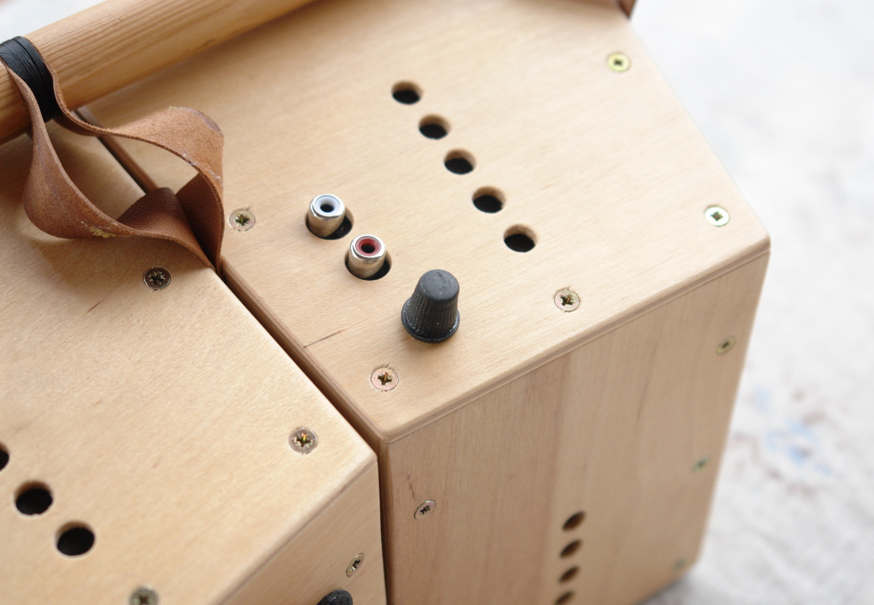
The core electronic components will sit in the left housing. I’ve needed a place for each and every component. I have drilled and filed the slots. Note, that when drilling, I’ve added a scrap peace under, to prevent chip-out.
I have drilled some decorative holes as vents. I’ve drilled from both sides again to prevent chip-out, and get a nice finish. These vent are needed because this type of power amplifier can get very hot. However I do not know whether it does good or bad impact for the sound quality.
I have added an extra piece here with some hooks to have the possibility of organizing the cables inside the case.
Magnets
The two sides finds each other by the help of 8 rare earth magnets. For the one side four of them were just glued on the panel with superglue. For the other side the idea was to sink the magnets below the surface, but it turned out that they need to be flush with the surface to match the other side.
First I was marked the place on the other side by applying some ink on the glued magnets before doing a test fit. Now that I know where to drill, I have drilled the sink-hole in this side. While gluing the magnets in these holes, I have attached them to the ones already glued. This way I have inserted all the magnets in the proper depth into the sink-holes.
In the end it turned out, that I have used a bit small magnets here. So you might want to try with stronger ones instead.
Grill
Unfortunately I did not had grill for the speakers, but this was a great opportunity to make my own design in the topic. So I have came up with a 3D-printer friendly solution, where the grill was built from two parts, and the two parts were glued together.
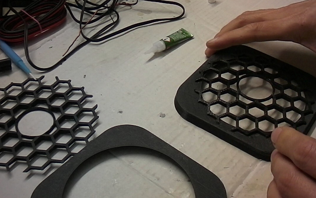
You can download the 3D object from here: http://www.thingiverse.com/thing:1818804
Handle
When the box was ready I immediately realized, that an object with a weight and a shape like this can not be carried without a handle.
I wanted a handle, that is functional in both attached and separated form. Further more in attached form, the handle should keep both sides together securely, as it turns out that the magnets let loose some times.
So the idea here, is to have a thin leather strip that connects the handle with the body, so the strips provide a flexibility. This way the two rods can be attached/separated with a twisting move.
I have designed and printed a 3D object for this twist-to-clip interlocking job.
You can download the design, and the 3D object from here:
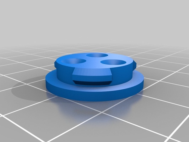
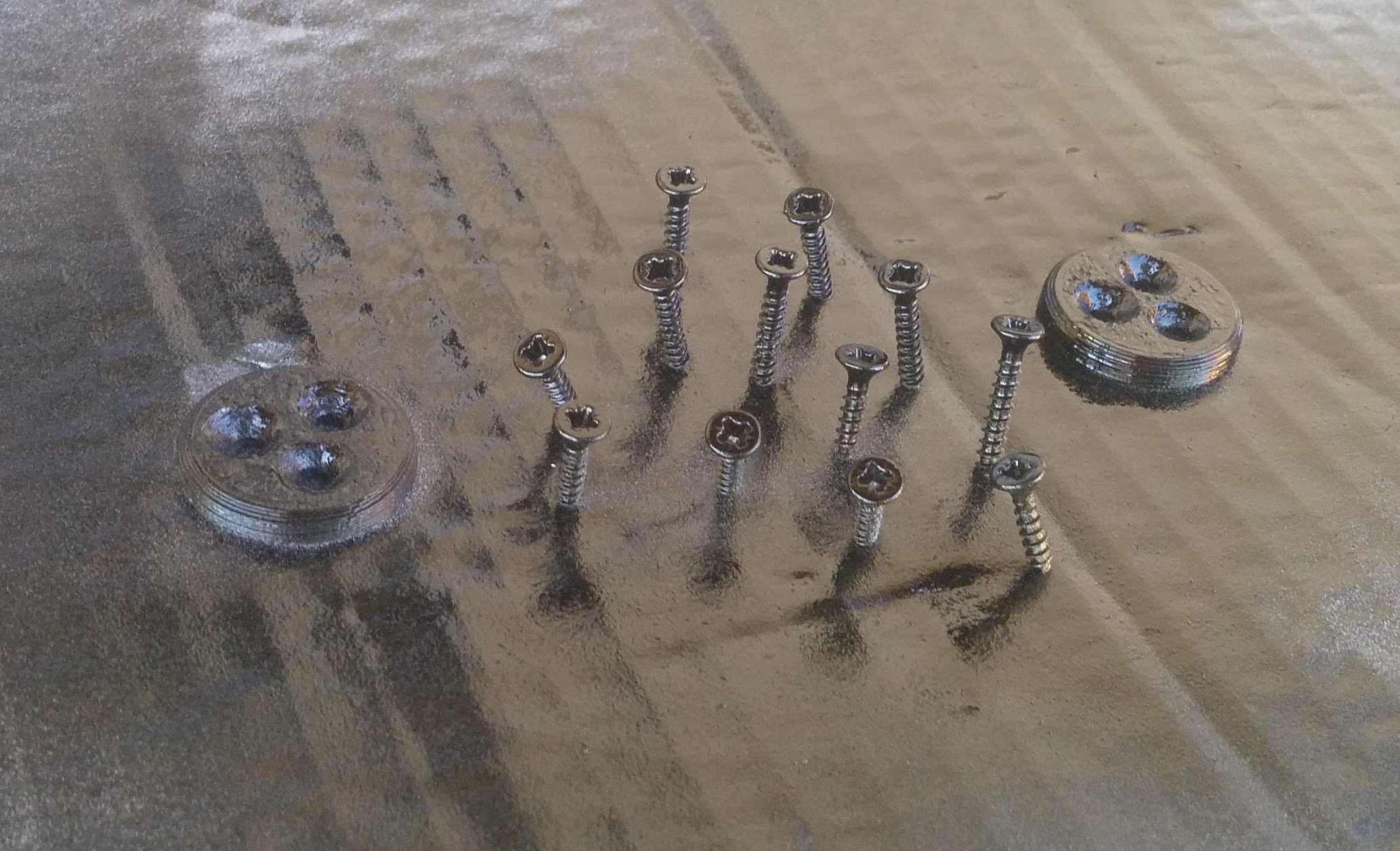
Finishing it up
As a final touch I have spray painted some screws to black, and 3D printed a knob to the volume control.
Video
The video about this build is separated into two episodes and can be found here: