Preface
Lately I play some chess again, and I was realized, that it will become very boring, if we do not limit the time of the game.
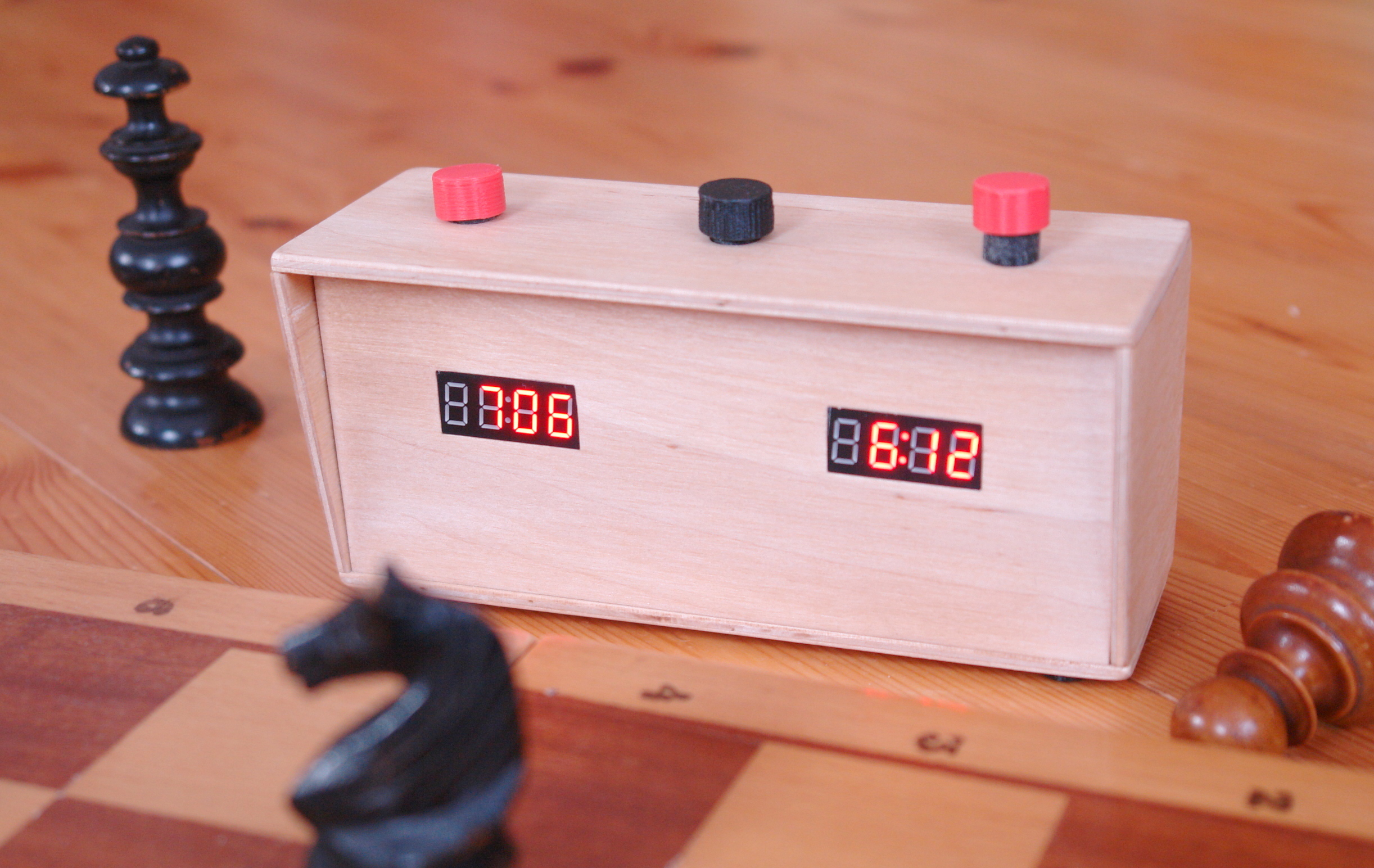
So a chess clock is required, but instead of buying one, it seams to be a great DIY project, and we will have a hackable clock around the house.
Button design
Chess clocks are often built with a tilting leaver on the top. But I’m always afraid of mechanical parts, and I wanted to experiment with solenoids, so I decided to use a non-conform solution (as usual).
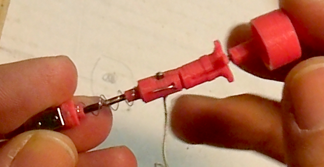
We need a solenoid that has a magnet on one end, and attracts the pin by default. But if we apply power to it, it can release the pin. The pin is connected to the push button. Than, we need a spring for keeping the button up, when released.
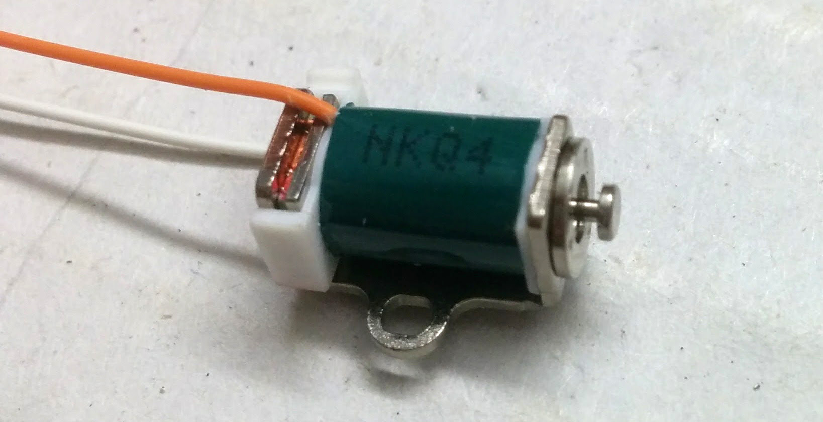
When the metal pin is down, it is connected with the magnet on base, that part of the metal case. So, if we solder a wire to the case, and a wire to the pin, this whole thing acts as a normally open switch, where pin is one lead and the case of the solenoid is the other lead of the switch.
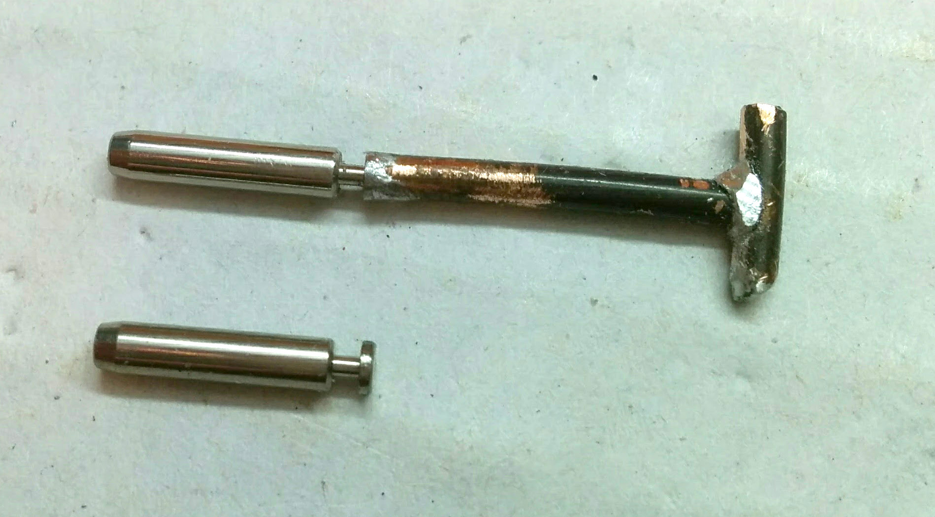
I have soldered a cooper bar to end of the pin, this is the length of the spring.
I wanted to use a spring from a ball-pen, but it was too hard, so I made my own spring from a guitar string.
3D design: http://www.thingiverse.com/thing:2156857
Case
The case is built out of 4 mm plywood.
For joining the faces, I glue on bars, in-which I can drive screws later on. I have used this method with success for my previous projects, and willing to be used in my upcoming case-projects as well. But this time I neither want to have visible screws on the front, sides and top faces. So in those joints I have glued two bars, and screwed them together. This was a bit tricky.
Also have glued on posts for the switches. These posts will also hold the electronics.
Download SketchUp design: ChessClock2.skp
Electronics
I have used the Arduino pro mini in a setup, where I can reprogram the clock later on. The wiring is very basic, I have used NPN transistors, to drive the solenoids. The inputs on the Arduino are pulled HIGH internally.
 The powering is built as a separate module onto the back face, and contains of a LiPo battery, a charger and a power switch. This is not an optimal solution, because the unit must be switch on for charging. Also, I just couldn’t find a plate-mount USB female socket in the market.
Software
I’ve use my own product, the SoftTimer library, as the core of the software. This comes a very handy, when I build time sensitive projects. (What is the case for most of the projects.)
You can download source code: ChessClock01.ino
Video
What’s next?
We are now have gadget with some special buttons and two numerical displays. This gadget can be reprogrammed, extend with other functions e.g. stopwatch, alarm clock (by adding a buzzer), electronic dice. Or maybe an IoT status display.
But first a battery level check support will be added soon, as the hardware is already prepared for this.