I already have shown how I have made an Arduino controller for my old LEGO robotic kit; and also, how to recognize colors.
Now I will form a cool project around these achievements, and build a line following robot.
This post focus on two key parts of the build: what is the recommended hardware design for this project, and how to build a proper Arduino software this job.
Hardware design
When we are about to build something physical, of course we need to have some idea in our mind. In this case the only thing I new, is that I want to build a car-like robot with a differential drive.
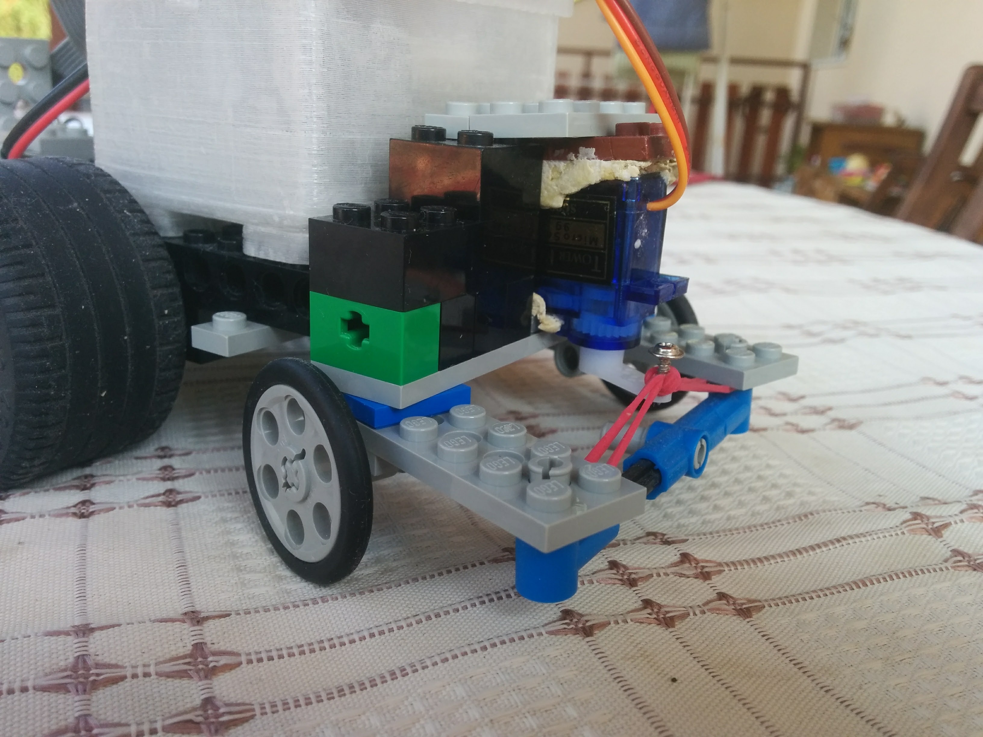
After some test runs, I have realized, that a regular car-like form is not ideal for this project, as is not capable to do narrow turns. It was clear, that I need to have the front and back wheels as close to each other as possible. But meanwhile I have come up with the idea, that the steering wheels should be on the back, to provide more dynamic response.
For mounting the servo motor, I have glued it on to some scrap pieces. The turning wheels are connected to the servo with a rubber band.
Software
The goal
We have a track, that is a white line. The goal is to follow the line with the rover we just have built.
Hardware capabilities
Let’s see what we have:
- We have two light sensors;
- We have a DC motor for the drive (with a H-bridge);
- We have a servo motor for the steering.
States
When building a small, easy-to-understand software like this, I like to use states. So what running states we will need to deal with?
- Both sensors are above the track.
- One sensor is above the track, but one is not.
- None of the sensors are above the track.
From the last two we have left and right variants.
When we are off the track with one sensor, we need to steer, to get back to the track. But when we are off with both sensors, we need to steer harder, to get back as soon as possible.
In a program life-cycle point of view, we have the following states:
- calibrating – As we are dealing with ambient-dependent measurements, before any other operation we need to have a calibration. (This can be a predefined thing, but it does not hurt much to do it every time the thing is turned on.)
- prepared – Calibration was done, we can start running.
- running – The track-states will determine the actions to take.
- track left – The “Running state” is ended because of some reasons. Most likely the track was left.
- error – It is a good idea to define cases, that means something went wrong.
Program parts
So our program consists of the following parts:
- Defining constants,
- Defining the states,
- Setting up local variables,
- Initializing the system,
- Determine the action should be performed according to the actual state,
- State manipulation methods – It is a good practice to modify the state in one specific method, and call this method to change the state.
- Other helper functions.
In our setup we have two kind of states, but the running state (or track-state) is not something that we can change. It is determined by the sensor values read.
Download the source code from here: LegoControl-PathTracker2
Conclusion
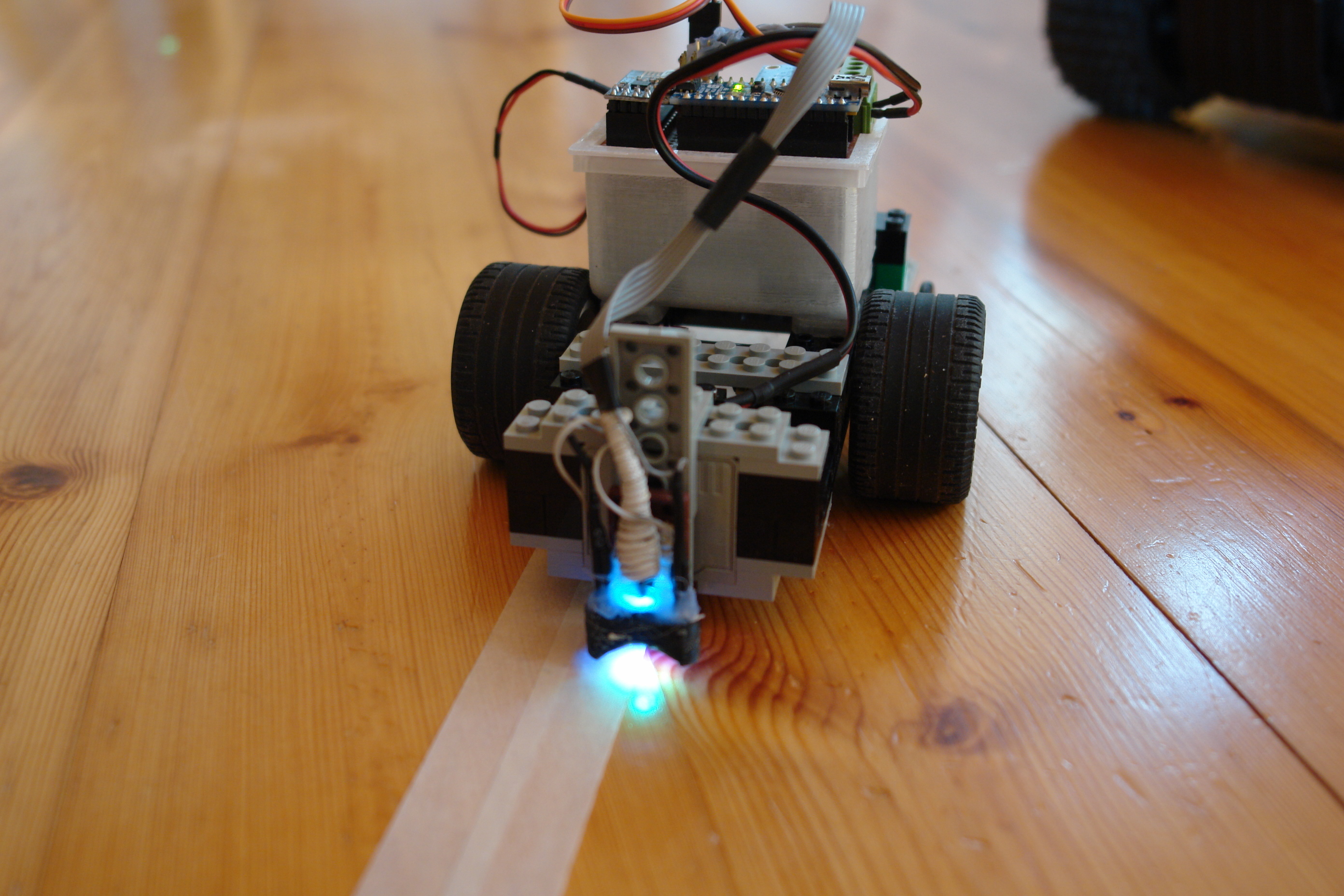
This program was just a proof of the concepts setup, whether I can solve a task with the hardware I have built around my LEGO kit.
The result is quite spectacular.
However, I need to note, that using a white colored line on a wood surface was not a very good idea. Especially as my sensors are capable to distinguish between colors. (So next time I will go and buy a blue painters tape.) But these are those small pitfalls you should to expect when programming physical hardware.