Sometimes you just need a special USB device for your computer. As your feet are always free, we wanted have a pedal device. The pedal device can act as a keyboard or as a mouse depending on your needs. Just think for the ones experience disabilities.
In our special case we wanted a device, that can send mouse clicks, when pressing the pedal.
Explanation
For small USB projects we have a nice tool called Digispark (with ATMega85). (For the record: We also have the Adafruit Trinket).
The Digispark is like a small brother of the Arduino, but it is especially useful to build cheep USB devices.
Very cheep Digispark clones can be found on online stores.
Costs (at Jan. 2018):
- Digispark board $1.25
- Pedal $2.30
- Potentiometer: $0.30 (can be any kind with 3 legs between 100Ω to 100KΩ)
Total costs is: $4
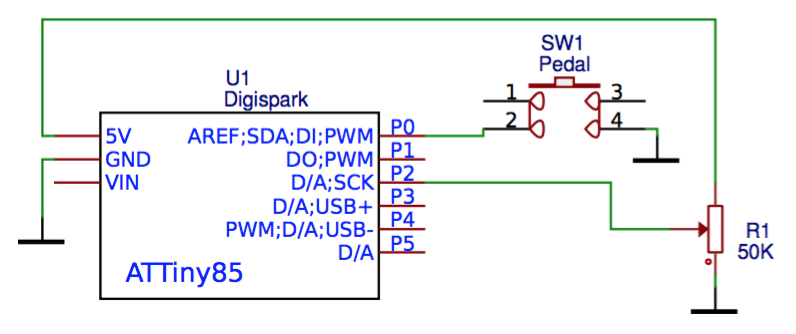
The ATMega85 has very limited capabilities. Is is barely enough to fill the needs of this project. We have added a variable resistor (potentiometer) to have some control on the device. This is the schematics of the wiring.
The pedal
We have bought the pedal online.
To disassemble it, you need to loosen the screw and push out the shaft. It comes with a useless piece of wire, that can be easily removed. As our project will use low power (5V), we are free to use any kind of wire laying around. E.g. this old-school telephone cord can finally find it’s place.
We also have added a small piece of tubing to act as a bend protector.
It is a bit tricky to close the pedal, but nothing special.
The case
For the case you can use any kind of plastic box laying around, but as we have 3D printer, we have printed one.
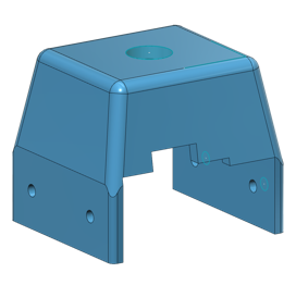
You can download the 3D design from here: https://www.thingiverse.com/thing:2760718
Assembly
First the Digispark board was mounted on a piece of hardwood (dimensions 27x28x12mm). This will add some weight for the box, so it is less likely to tip.
Then all the connections are to be soldered.
The potentiometer was mounted in the case, and the case were closed.
Software
For the software part, you can directly upload the program to the device from the Arduino interface as far you have done the following steps.
- Have the appropriate firmware installed to your Digispark board (what in all the cases done in the factory) (See for reference: https://github.com/micronucleus/micronucleus)
- Have the Digispark board-manager added to your Arduino IDE (by following the steps in http://digistump.com/wiki/digispark/tutorials/connecting) (Board manager URL: http://digistump.com/package_digistump_index.json)Windows users! You also need to install a driver.
First we have uploaded a code, that helps calibrating the potentiometer values. This code will “type in” the current analog values read from the potentiometer.
Test program for finding out values: PedalDevice-IoTest
Actual program: PedalDevice-Click02
After that, the clicking code was uploaded, and we are ready to roll. (The code contains a software debouncing solution.)
Click-hack
The current program we are using for the device | is a kind of click-hack. It will send rapid clicks. You can set the CPS speed by adjusting the knob on the device. When you turn the knob to the right side, it will send right clicks. On the left side, left clicks are sent.
The internal LED flash-speed denotes the CPS value set.
Disclaimer: Please do not use this solution in online games (where pedal devices are not allowed 🙂 ), as you will likely to be banned, but more importantly: Play fair!
Pitfalls
- The D5 pin of the Digispark was marked as analog input, but it is the reset pin of the ATTiny. So lower values will cause reset. Instead pin D2 should be used.
- The analog read of the ATTiny85 is a bit odd. E.g. in our case we used D2 for reading analog values, but for analogRead number 1 was needed to be queried.
- Always call the DigiMouse.update() method, even when it does not seem to be required.
Video