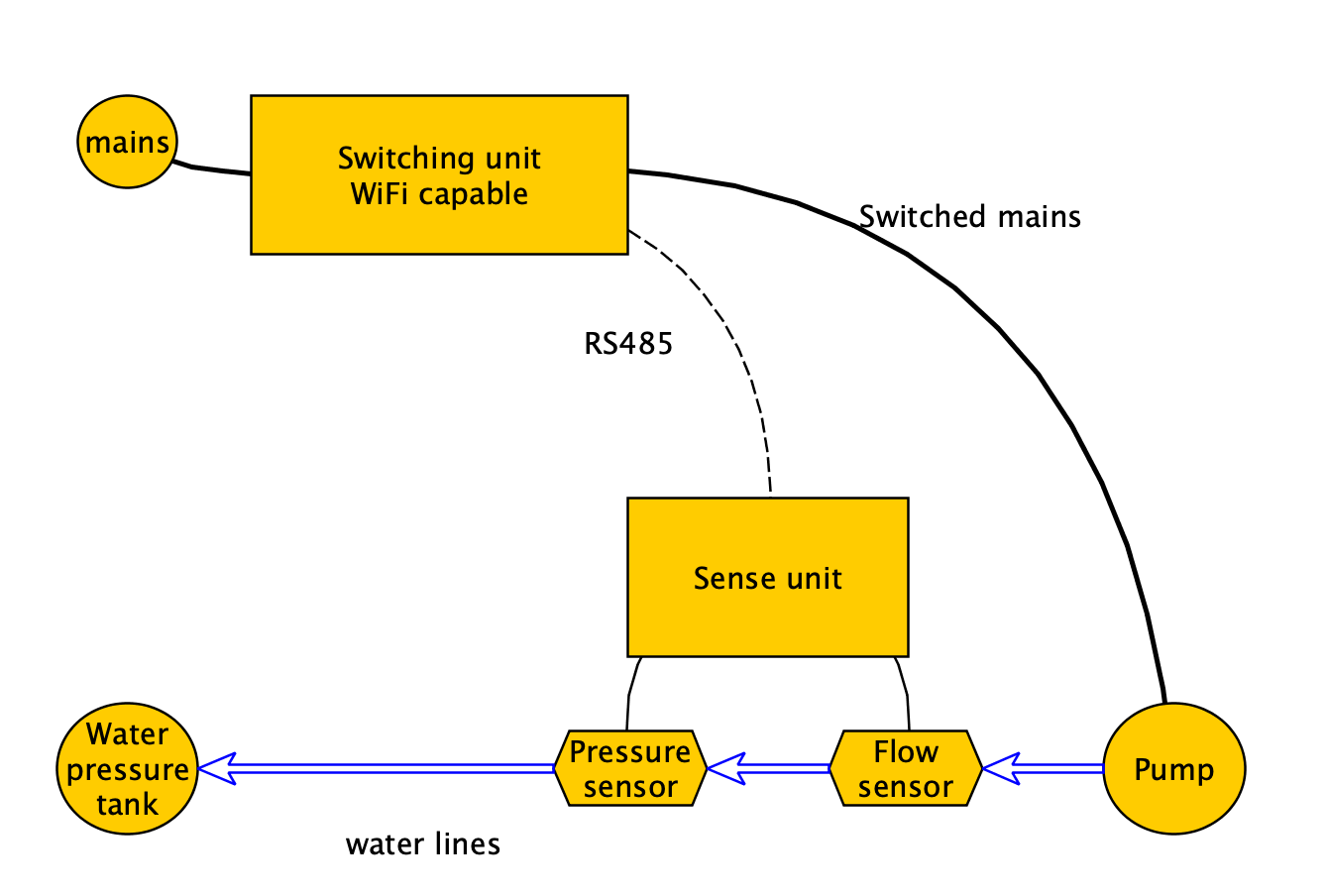
I have built a water flow controller with two home made panels made around the Arduino infrastructure. One unit is near the sensors measuring flow and pressure, the other one communicating on my home automation network. The two units are connected with RS485.
Preface
I had a water pump with some generic switching hardware, that had some disadvantages:
- There is no feedback on the status, no logs.
- Very limited safety features.
- At On/Off a pressure impulse appears in the system. Traditional hardware tends to false-trigger on these waves casing the system to turn on after it was just turned off.
- Eventually it failed.
So I’ve decided to build my own controller setup.
Please also visit post Designing the Water pump controller PCB for the PCB considerations of the same topic!
Requirements
I have set up the following requirements for myself.
- Must measure pressure, water flow. (Actually there are two water lines to measure flow on.)
- Must switch pump on measured pressure levels. (Turn on, when pressure drops under a specified level; turn off, when a specified top-level reached.)
- Must have some intelligent features: ignoring pressure impulse, and safety features (see below).
- Must report flow (actually two flows) to the home automation system with MQTT.
Safety features are:
- Dry-run detection: Motor is on, but flow is dropping.
- Leak detection: Motor is on for too much time.
- Catastrophic error detection: Motor is running, but pressure is dropping.
The safety features should be parameterized.
Now it turns out, that my water line is a location, where WiFi will not enter. further more, the humidity is extreme, and even with the best sealing, moister will eventually kill electronics. This is why I have decided to have a two-unit design. There is one unit very close to the sensors. This unit is cheap, and can be replaced, when needed. The switching unit is in a safe location. The switching unit switches the pump motor on/off and also performs all the communication tasks.
Hardware
Bill of Materials
I have used cheep sensors, and build the units around cheap micro-controller modules.
- Pressure sensor – G1/4 DC5V 0-1.2 MPa
- Flow sensor – 1 Inch Hall Flow Meter
- Custom made PCB and components for two units. Highlighting:
- Wemos D1 Mini
- Arduino ProMini
- Omron G6RN-1 12V DC relay for switching 8A at 250V AC
- HiLink HLK-PM12 for transforming mains to 12V DC for 0.25A
(* Affiliated links)
Pressure sensor
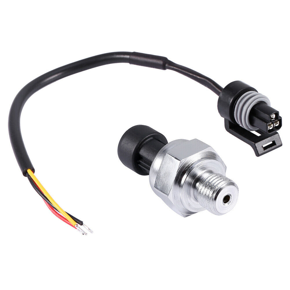
This module has a 1/4″ threaded part to fit on the water line, has a ground and power line (5V) and a sense line. The module varies the voltage on the sense line according to the pressure. The correlation is linear. The sense line is connected to an analog pin on the Sense-unit. It took me some measurements to calibrate, I have used my air compressor to set up some certain pressure levels, so I could calculate the correlation between measured analog value and actual pressure in Bars.
This module features a nice water-tight connector, but the provided cable is extremely short. I have used some shielded cable to extend it. The join was covered by high quality silicone and shrink-tube.
Water flow sensor

This module features a 1″ tube containing a rotor, that has a magnet built in. Outside of the tube there is a Hall-effect sensor mounted. For our purpose the effect of the sensor is to go HIGH/LOW on every turn.
Again the cable of this module is too short, so I have dismantled the external container and soldered my wire directly on the exposed terminals. The external container was then filled with high quality silicone.

Do not use aluminium combined with copper because of the different electrode potential of the two materials will cause extreme rapid corrosion of the aluminium. Best is to avoid aluminium fittings for good.
Sense Unit
The Sense unit tries to be as simple as possible. It utilizes an 5V Arduino Pro Mini. 12V comes from the Switching unit, that is transformed by the onboard regulator to 5V. These voltage regulators are known to be very reliable. It generates some heat (not much, as the power consumption is low), but in a humid environment it is a plus.
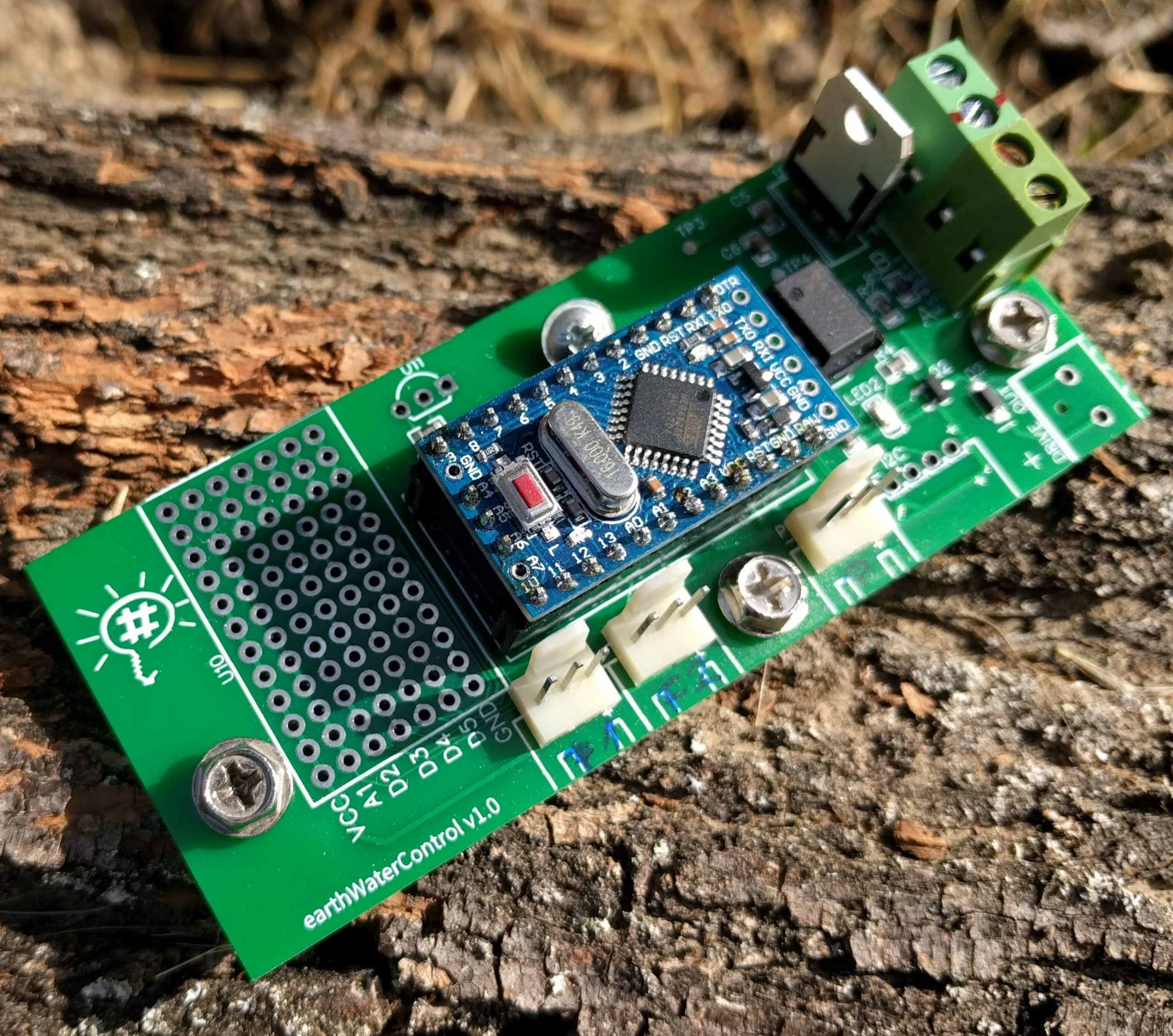
I have chosen RS485 for the communication as RS232 had some data quality problems with longer lines and it also requires more space on the PCB board.
Switching Unit
The main component of this setup is the Switching Unit. It has a direct AC mains input, utilizes an onboard AC to 12V DC converter and a Wemos D1 Mini ESP8266 microcontroller module.
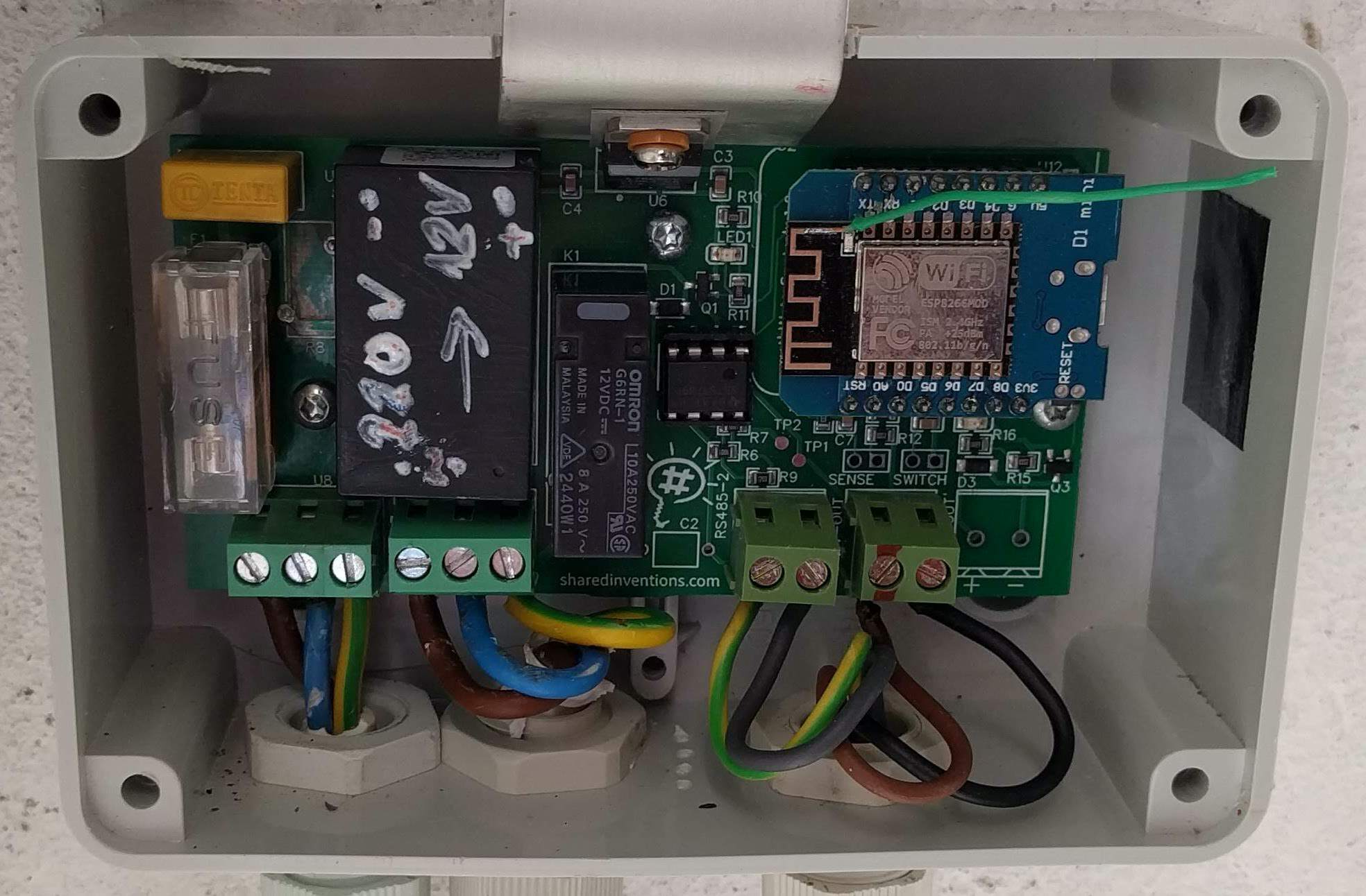
As you can see on the photo, the package of the AC/DC converter was a fail. It was wrapped in a plastic foil that was integrated into the painting of the module. As I was trying to clean up things, I was totally vanished the writing from it.
Again used a good quality voltage regulator to get 5V for the Wemos D1 Mini, and for other parts. But this time the power consumption will be significant, so I’ve also added some bent aluminium sheet to direct the heat outside the case.
I use a very good quality switching relay.
So the board has a direct mains input, it powers the low-voltage parts from it and also directs it forward to the pump motor via the switching relay. (Connectors on the left.)
This unit also provides 12V power for the other unit, and the RS485 communication also requires two cables. (Connectors on the right.)
You can fine more hardware considerations in post Designing the Water pump controller PCB!
Software
Sense unit
The sense unit contains some very basic software. It collects sensor data and sends it to the Switching unit via RS485. The communication is one-way only to keep things simple. Data was sent in every second (!).
For the pressure sensor the actual raw data is sent. For the two flow-sensors there was one interrupt-handler was set up each, basically counting the turns of the internal rotor of the sensor since the last package was sent. (Actually every half-turn was counted.)
Source code:
waterPumpMinimal.cpp
Switching unit
Convert raw data to metric units
Sent data was received from the Sense unit, and the pump-motor was controlled by a specific logic. Meanwhile WiFi commands are handled, log is sent to the Home automation network, safety checks are done.
Sense-unit sends raw sensor data to the switching-unit every second. Data was converted to some more convince units.
- Pressure is an analog value sensed from 0-5 Volts and represented in an integer value between 0-1023. Now it turns out (with some measuring), that this value can be converted to Bars (metric unit) with the following equation: ((float)sensorValue – 152) / 67 is the measured Bars value. As you can see we have an offset of 152 in the sensed value, so everything below number 152 can be counted as zero Bars.
- Flow is rotation action counter of the sensor within one second. (Actually two events counts as one rotation.) I have measured the following equation: eventCountPerSec * 0.00114 will result the liters of fluid passed within that very second. This value is unfortunately very much dependent on the speed of the flow, so I couldn’t found this sensor to be usable for actual consumption measuring. It is still great to detect flow-oriented correlations.
As mentioned above, sensed data should be arrived at every second. If one packet is missing (and we are in the middle of an action) the previous value is reused instead, thus simulating (and assuming), that nothing is changed in the lost second.
Normal operation and safety features
The main goal of the whole setup is to keep a constant pressure in the system. We have a lower threshold value, where the pressure drops under this pressure, the pump motor is started to let the pressure raise. There is now a top pressure threshold value, where the pumping stopped if the pressure exceeded this value. (The pressure will constantly dropped, as water is used from the system.)
Now starting and stopping the motor causes a huge pressure transient in the pipe-system. E.g. after stopping the motor at the top threshold value, pressure may be dropped under the low threshold value for a brief moment of a shock-wave. There is a PRESSURE_WAVE_MS constant in the system, where after starting or stopping the motor, any new event should be omitted within this period.
Some safety functions are introduced according to the requirements. If one of the safety checks resolves an issue, the problem is raised, and the unit will enter a Stand-By mode. A manual interventions must be performed to leave this state and continue normal operation.
Actual safety features introduced. Error state is entered when …
- No data arrived from Sense-unit within SERIAL_PROBLEM_MS milliseconds.
- Pump does not stop for a decent amount (minutes). (runawayTimeMins)
- A certain time (DRYRUN_DETECTION_MS) was passed since starting to pump, but pressure was not reaching the lower threshold value.
- Pressure drops under a specific value (DRYRUN_PRESSURE_BARS) while pumping.
- Water flow drops under a certain value (flowMin) while pump is running.
- Emergency stop button is pressed. Or emergency stop MQTT command is received.
Source code: iotWaterPumpController.cpp