As mentioned in post Water pump controller I was building a system, that controls the water pump and connects to my Home Automation network. The system contains of two units. One is near to the sensors in a humid environment where there are no network coverage, the second unit performs the switching in a safe location with WiFi coverage. The two unit is connected with RS485
It turns out that ordering a custom designed PCB does not cost more – even with placed SMD components – than if you count the hours you spend soldering into a proto-board. On the other hand, if you order a PCB, you want to be sure, the result is near perfect, and you might end up to be feature-creep.
This article is about the design decisions made while producing the two PCBs for the Water Pump system.
Microcontrollers
The Switching-unit must communicate on WiFi, so an ESP8266 is a reasonable pick. I like to utilize the Wemos D1 mini system, as it is compact and easy to use, it is cheap and can be replaced easily in case of any trouble.
The Sense-unit must be something very minimalist and very reliable. Arduino Pro Mini (5V) is chosen, again it is compact, cheap and easy to replace.
Power management
While the Switching-unit handles mains, it is reasonable idea, to get its power from the mains, the Sense-unit will have to receive DC voltage. The sense unit works on 5V, and receives it’s power from the Switching-unit (along the RS485 lines) on a long cable, so it is a good idea provide more juice on the cable then 5Volts. So 12V will be provided from the Swithing-unit for the Sense-unit, and an onboard LM7805 voltage regulator will produce the required 5 volts. These regulators are very reliable, and however it generates some heat, this time (humid environment) it might have some benefits, as the water will not condensate on warmer objects.
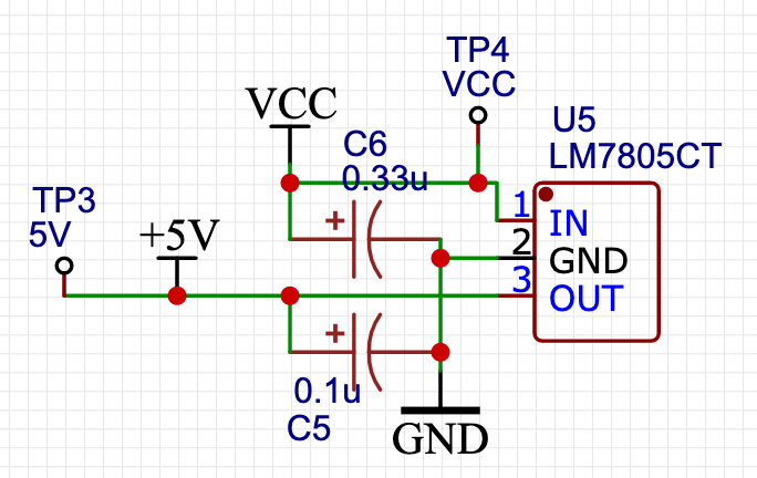
So, there will be a mains-to-12V/DC power supply integrated into the Switching-unit, that provides the 12V for the Sense-unit power. 12V/DC will also be great for the Relay solenoid, that turns on/off the motor. For the Wemos D1 Mini, again 5V is required, and again the LM7805 will be utilized here. This time the heat dissipation will be more noticeable, so a heat-sink should be applied for the voltage regulator.
A HiLink HLK-PM12 (clone) is used for converting mains AC voltage to 12V DC.
As we are talking about mains…* There are some safety/protection components included. (Safety features are not applied for the switched lines.)
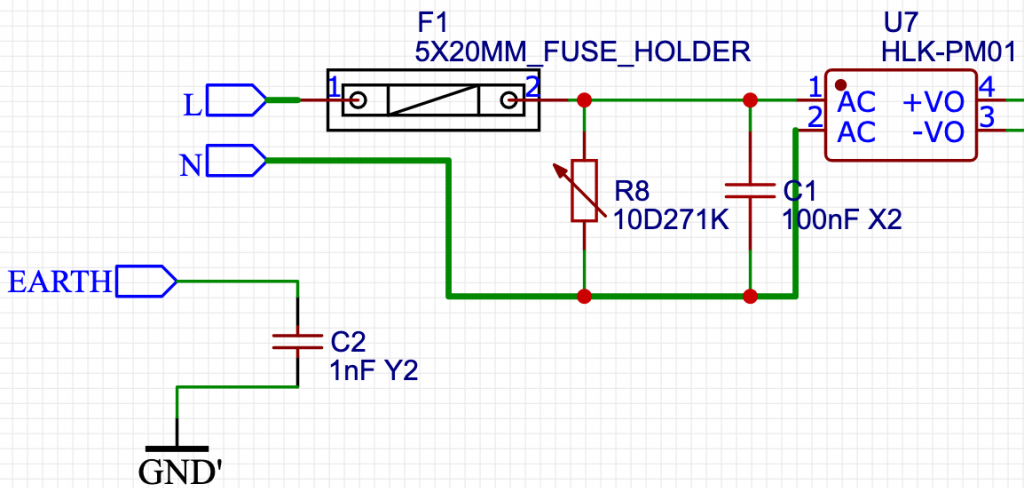
- Fuse – The AC input of the board is fused.
- A 100nF X2 capacitor is added between line and neutral
- A 10D271K varistor is added between line and neutral – This varistor should have protected the board from over voltages, but it just have blown up immediately after power-up in my setup. I might have ordered something different, or I just have received faulty items.
- A 1nF Y2 capacitor is added between earth and DC ground. – Actually this resistor is not populated, as I couldn’t find one to order.
* WARNING! Do not use work with mains voltage if you are not comfortable with it. Inappropriate handling of mains voltage is lethal. Also note, that I’m not an expert myself, so do not rely on my recommendations!
Instead of AC, DC input can be directly connected to VCC-IN terminal.
Communication link
Originally I wanted to use RS232, but is requires more pins, takes up more place from the PCB and eventually it suffered with data-problems over a long cable while testing. So, I moved to RS485, and I cannot be happier about this decision.
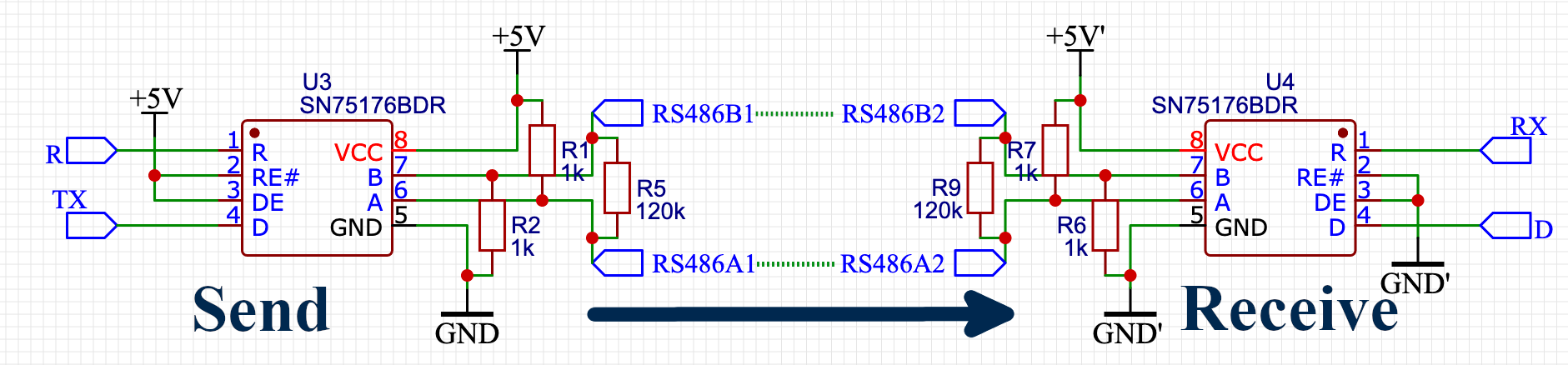
This is a very simple setup, as we are communicating on one direction. The RE- and DE legs of the modules are hardwired according to this. (Note, that RS485 is a bus system, it meant to connect multiple units talking to each other on the same line, so it can do way more things than we show here.)
The R leg of the sending module, and the D leg of the receiving module are not used. The D leg of the sending module is connected to the TX on the Arduino Pro Mini on our Sense-unit, the R leg of the receiving module is connected to the RX on of the Wemos D1 Mini on the Switching-unit. Note, that while the ESP8266 operates on 3.3 Volts it is known to be safe to connect 5V logic level input on digital pins, like the RX.
Another thing to notice, is that if we connect to the RX and TX legs on the microcontrollers, we are ending up blocking serial debug and upload software from serial. Fortunately the microcontroller modules are detachable, so we can remove them for programming. Or next time we can design to have the R leg of the receive module to the D7 leg of the Wemos D1 Mini (and possibly leave D8 unconnected), as we have a Serial.swap() option, where we can redirect Serial communication from RX, TX to D7, D8.
You can spot the pull-up and pull-down resistors for the A/B lines, and the 120K terminating resistor is also populated, as these are the terminating-units of our RS485 “network”. (And also, we can always desolder an SMD resistor in case we would like to build a real network.)
Peripheral options – Sense-unit
Pressure sensor
The pressure sensor is really easy to connect. It will provide a voltage level between 0 and 5Volts (supplied power voltage level), so it is connected directly to the Arduino analog input A0. A separator resistor might have been a good idea to add in series (as there is no actual current flow here), but not necessary.
Conversion from raw sensor data to pressure units is done in the software as described in post Water pump controller.
Flow sensor
There are two slots for connecting two flow-sensors. The flow sensor is a Hall-effect sensor, that will change the connected pin value HIGH to LOW and then HIGH again in one revolution of the internal rotor.
Again, the flow-rate per seconds are calculated by the event count using a hard-coded formula as mentioned in post Water pump controller.
Originally flow-sensors are connected to pin 8 and 9, as I wanted to solve the change-event handling with pin-change-interrups. But somehow I couldn’t manage to get that work, so I used attachInterrupt(). Now it turns out, that attachInterrupt() works only in pin 2 and 3 in this microcontroller, so I also quickly rewired these pins, and marked pin 8 and 9 as inputs.
External I2C connector
There is an I2C connector populated to attach e.g. a humidity sensor to the system. This is not used in my current setup.
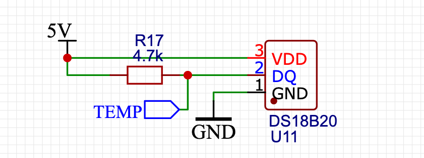
OneWire connector
A OneWire connection option is provided in a form of a TO-92-3 footprint. A DS18B20 temperature sensor can be directly connected to this area.
Drive-out
There is a controlled power-output provided. With ping D6 one can control external consumers on VCC power (that is about 12Volts). With the integrated MOSFET (2N7002) a 0.1 Amps load can be driven up to 60 Volts.
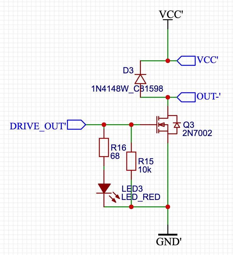
The idea behind this output is to drive an external fan in case we are detecting big humidity. But after all this might not be a great idea, as fresh warm air will condense out water on cold objects like water pipes, making thing much worth.
Prototyping area
To fill out the left over place, a prototyping area is formed with exposing 5V, GND and pins A1, (D2), (D3), D4, D5. (D2 and D3 pins are meanwhile used up by the flow sensors.)
Peripheral options – Switching-unit
One wire connector
As mentioned at the Sense-unit a OneWire temperature sensor can be directly connected to the dedicated pin-holes.
Drive out
Besides controlling the relay, a similar circuit is provided to control something external, like a fan. Please check “Drive out” section of Sense-unit, as all properties mentioned there also applies for this circuit.
Drive-out is controlled by pin D2.
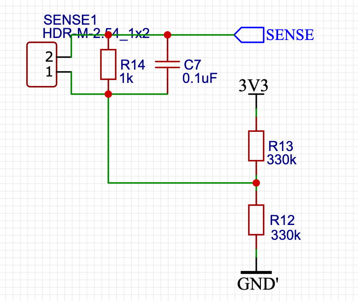
Detect mains load
On D7 one can attach a current transformer to sense if there is a load on the switched line. As the line is oscillating with mains 50Hz, changing in the line means, there is a load. This can come handy to detect motor failure.
Details on current transformers can be read in post Shade controller.
External switch
A switch can be mounted on connector SWITCH1, that is connected to pin D8. Switch bouncing is reduced by a small capacitor.
Inspection and modding options
According to my experience, it is always a good idea to provide as many modding options as possible. I also like to provide some test points. Beyond that is great to troubleshoot with test-points, test-points are also great possibilities to mod the system, e.g. find 5V power line.
The Sense-unit provides a whole prototyping area for extensions, along with an external i2c connector.
Switching unit has four extra rows next to the microcontroller slot: all pins are exposed in 1-1 lines, 3.3V and GND are exposed in two more lines.
Both units can be extended with oneWire sensors.
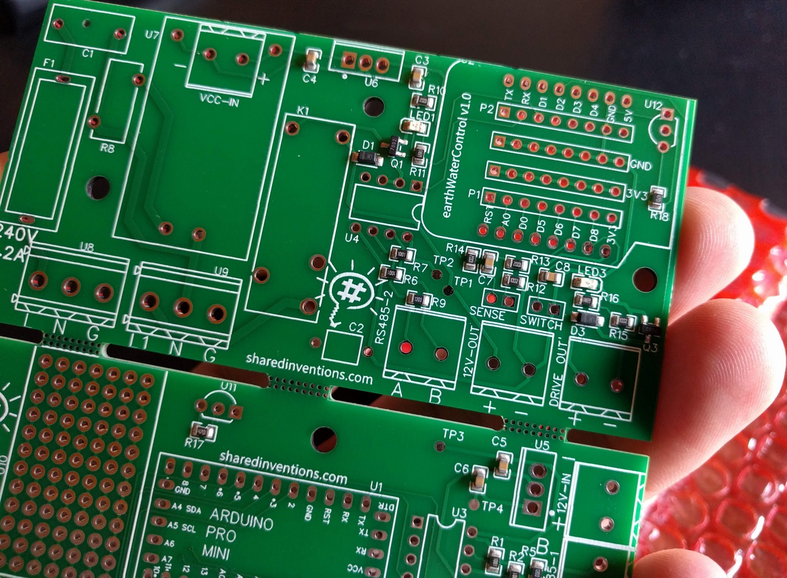
PCB
With this batch I wanted every SMD parts to be soldered on onto the board by the manufacturer. The quality of their soldering is way better than mine, and the price of used components are extremely low.
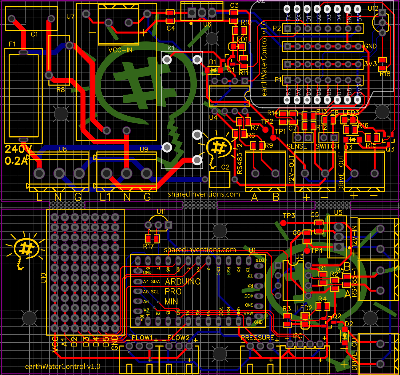
As this is a two-unit setup, it made sense to place both units onto one PCB. The standard PCB size at JLCPCB is 100mm x 100mm, that is more than enough for both the units. With the Sense-unit, I was even able to prepare a prototyping area on the leftover place. The two units are separated by a cutout, but joined with three perforated gates.
Overall I’m very satisfied with the product outcome.
Known bugs in PCB v1.0
- The switched mains lines could have been more thick, even unmasked, so I could have added some extra solder on the lines to provide more current flow. I needed to add wires here, to be on the safe side.
- Instead of D8 and D9, the flow sensors should have been connected to D2, D3 of the Wemos D1 mini, as mentioned above.
- Instead of RX, TX, the digital pins D7, D8 should have been used for the RS485 in the Wemos D1 Mini, to have both serial programming work and with Serial.swap() the the communication could have redirected to D7, D8 pins.
Pingback: Water pump controller – Shared Inventions